Rockwell Automation Publication 520-TD002A-EN-E - May 2015 3
PowerFlex 527 AC Drive Specifications
• A jumper to switch between 24V DC sink or source control for control wiring flexibility.
• Dual Overload Rating available for drives above 15 HP/11 kW. Normal duty: 110% overload for 60 seconds or
150% for 3 seconds. Heavy duty: 150% overload for 60 seconds or 180% overload (200% programmable) for
3 seconds provides robust overload protection.
• Adjustable PWM frequency up to 8 kHz ensures quiet operation.
PowerFlex 527 AC Drive Advanced Features
Control Performance
• Frequency Control with the following options:
• Volts per Hertz (V/Hz)
• Sensorless Vector Control (SVC)
• Sensorless Vector Control (SVC) Economizer
• Position Loop, including:
• Closed Loop Position Vector Control (with optional encoder card)
• Velocity Loop, including:
• Closed Loop Velocity Vector Control (with optional encoder card)
I/O Wiring
• Two (2) Analog Inputs (one current and one voltage)
are independently isolated from the rest of the drive
I/O.
• Four (4) Digital Inputs provide application versatility.
• One (1) Analog Output is jumper selectable between
either 0-10V or 0-20 mA. This scalable, 10-bit output
is suitable for metering or as a speed reference for
another drive.
• Two (2) Opto Outputs and two (2) Relay Outputs
(one form A and one form B) can be used to indicate
various drive, motor or logic conditions.
Communications
• Built-in dual port for EtherNet/IP allows easy
configuration, control, and collection of drive data over
the network. It also supports Device Level Ring (DLR)
topologies, providing fault-tolerant connectivity for
optimum drive availability.
• Online EDS file creation with RSNetWorx™ providing
ease of set-up on a network.
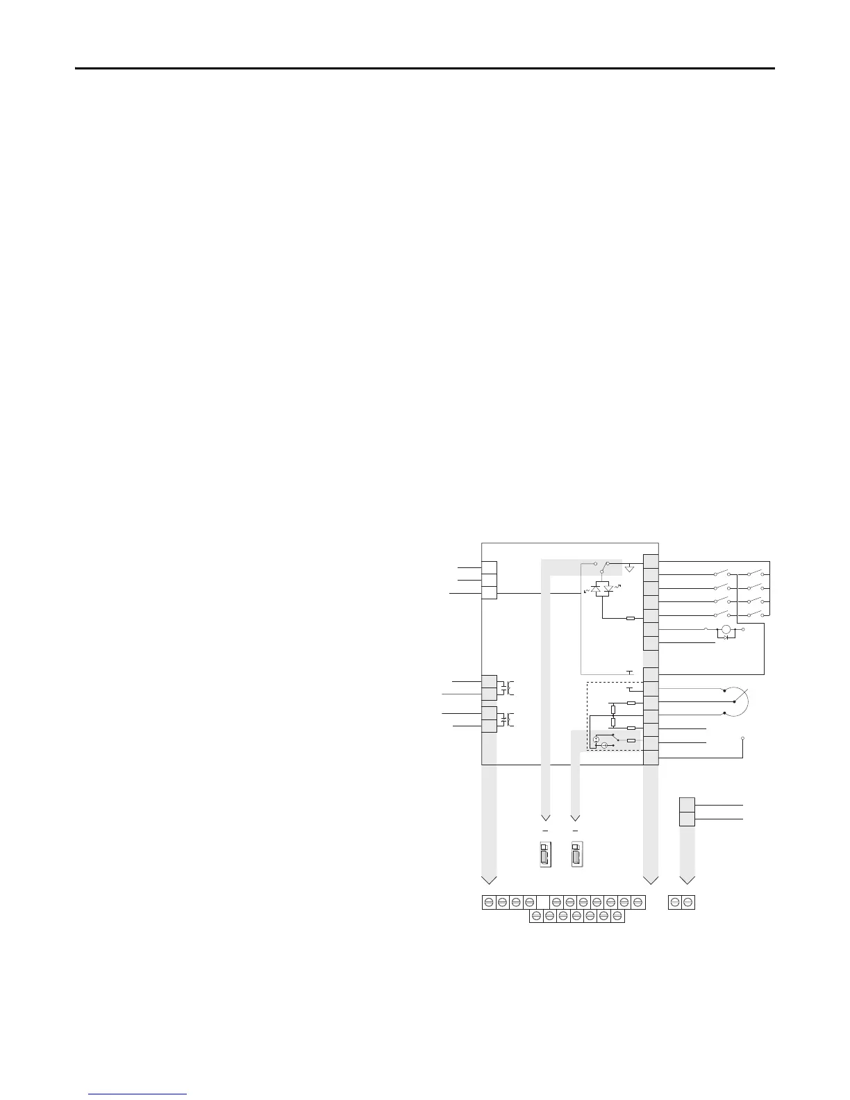
PowerFlex 527 Control I/O Wiring Block Diagram
R1
11 12 13 14 15 16 17
R2 R5 R6 01 02 03 04 05 06 07
C1 C2
04
05
06
07
01
02
03
11
12
13
14
15
16
17
Digital Common
Digital In 1
Digital In 2
Digital In 3
Digital In 4
R1
R2
S1
S2
S+
Relay 1 N.O.
Relay 1 Common
+24V DC
+10V DC
±10V Input
Analog Common
4-20mA Input
Analog Output
Opto Output 1
Opto Output 2
Ethernet
Comm Common
Opto Common
+24V
+10V
Safety 1
Safety 2
Safety +24V
Typical
SNK wiring
Typical
SRC wiring
Pot must be
1...10 k ohm
2 W min.
0-10V
0/4-20 mA
SNK
Digital In
Analog Out
J2
J1
SRC
ACO
AVO
SRC
SNK
R5
R6
Relay 2 Common
Relay 2 N.C.
C1
C2
Common
24V
(1)

 Loading...


