Rockwell Automation Publication 750-PC108A-EN-P - April 2021 11
PowerFlex 755T Drives Configured to Order Program Product Information
Recommended Mounting Hardware
See the PowerFlex 755T Drives Configured to Order Program Installation Instructions, publication 750-IN118. That publication provides information on mounting the bays with either a Rittal corner base/plinth system or a
structural steel system.
Shipment Sections and Approximate Weights
Products are divided into sections for shipment. One or more bays may be included in each section. Information on how your product was divided is available in the drawings that came with your product. There are two
ways to find weight information about your product:
• The weight of each shipping section can be found on the shipping slip for that section. You can find the weight of your entire product by adding the weight of the shipping sections.
• The approximate maximum weight of each configured bay is listed in the following table. The approximate weight of the drive bays is listed in the PowerFlex 750-Series Products with TotalFORCE Control Installation
Instructions, publication 750-IN100
. You can find the weight of your entire product by adding the weights of all the bays.
Weight information is important when making sure your transportation equipment is rated to move the bays. See Move the Bays
on page 46.
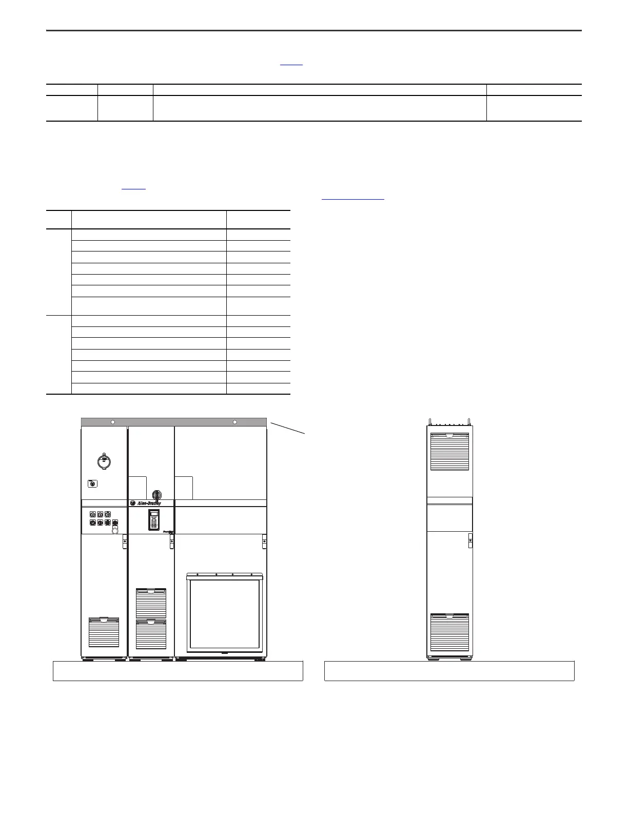
Figure 15 - Example Shipping Sections
Frame Size Fastener Size Usage Notes
Frames 8…9 M12 (0.5 in.)
• Secure the bay to the mounting system (corner base/plinth system or structural steel) by threading the fastener into the bay
mounting hole.
• Secure the mounting system (corner base/plinth system or structural steel) to the mounting surface.
Property Class 8.8 or better
(Grade 5 or better)
Frame Configured Bay Size
Approximate Maximum
Weight, kg (lb)
8
Configured input bay, control-only 93 (205)
Configured input bay with fuses, top entry 114 (252)
Configured input bay with fuses, bottom entry 116 (255)
Configured input bay with circuit breaker, top entry 113 (249)
Configured input bay with circuit breaker, bottom entry 114 (252)
Configured output bay with contactor only, top or bottom exit 78 (172)
Configured output bay with sine-wave filter and contactor, top
or bottom exit
485 (1069)
9
Configured input bay, control-only 93 (205)
Configured input bay with fuses, top entry 290 (639)
Configured input bay with fuses, bottom entry 290 (639)
Configured input bay with circuit breaker, top entry 175 (386)
Configured input bay with circuit breaker, bottom entry 221 (487)
Configured output bays, top exit (two bays together) 1065 (2348)
Configured output bays, bottom exit (three bays together) 1121 (2471)
Roof exhaust vents are
detached for shipping

 Loading...


