Rockwell Automation Publication 750-PC108A-EN-P - April 2021 17
PowerFlex 755T Drives Configured to Order Program Product Information
Grounding Requirements
The Safety Ground-PE must be connected to system ground. Ground impedance must conform to the requirements of national and local industrial safety regulations and/or electrical codes. Periodically check the
integrity of all ground connections. For more information on grounding requirements, see PowerFlex 755TM IP00/Open Type Kits Installation Instructions, publication 750-IN101
, and Wiring and Grounding Guidelines for
Pulse Width Modulated (PWM) AC Drives, publication DRIVES-IN001
.
Recommended Grounding Scheme
A single point (PE only) grounding scheme should be used. The jumpers (PE-A and PE-B) in PowerFlex 755T Configured Drive are set to be a solidly grounded system. Some applications may require alternate grounding
schemes. For information on alternate grounding schemes, see Wiring and Grounding Guidelines for Pulse Width Modulated (PWM) AC Drives, publication DRIVES-IN001
. The drawing package that came with your order
contains a schematic that provides grounding information. See that schematic for specific grounding recommendations.
The typical grounding information for a PowerFlex 755T Drives Configured to Order Program product is the same as the typical grounding information for a solidly grounded 755T standard product. Grounding information
about the 755T standard product is available in the Recommended Grounding Scheme section in the PowerFlex 750-Series Products with TotalFORCE Control Installation Instructions, publication 750-IN100
.
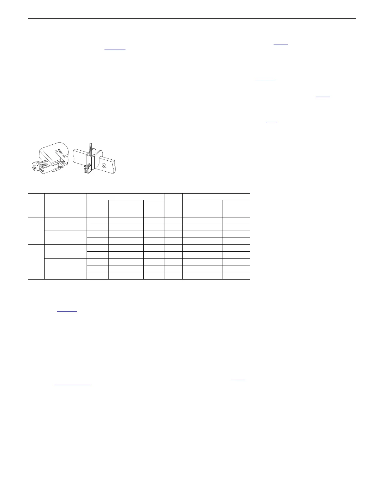
Grounding Clamps
Grounding clamps are provided with your product. You can order additional grounding clamps from Rockwell Automation or Rittal using the order information in Table 6. The grounding clamps can be used to secure round
copper ground conductors to 9.5 mm (0.37 in.) thick ground busbars.
Figure 16 - Grounding Clamps Provided with the Product
Shield Termination - SHLD
There is at least one PE ground bar in all configured input bays with input protection, and all configured output bays. A PE ground bar is the terminating point for incoming AC line and motor cable shields. The motor cable
shield must be connected to an earth ground by a separate continuous lead. Connect the other end of the motor cable shield to the motor frame. See Wiring and Grounding Guidelines for Pulse Width Modulated (PWM) AC
Drives, publication DRIVES-IN001
.
RFI Filter Grounding
Using an optional RFI filter may result in relatively high ground leakage currents. Therefore, the filter must only be used in installations with grounded AC supply systems and be permanently installed and solidly
grounded (bonded) to the building power distribution ground. Be sure that the incoming supply neutral is solidly connected (bonded) to the same building power distribution ground. Grounding must not rely on flexible
cables and should exclude any form of plug or socket that would permit inadvertent disconnection. Some local codes may require redundant ground connections. The integrity of all connections should be periodically
checked. See the instructions supplied with the filter.
Electrical Connections Made to Each Configured Bay During Installation
This section provides a summary of electrical connections that must be made to each configured bay during installation, including connections to other bays and connections to customer power source and motor. Make
the connections in this section as described in PowerFlex 755T Drives Configured to Order Program Installation Instructions, publication 750-IN118
. This section does not include all grounding connections. For grounding
connections, see Grounding Requirements
.
Table 6 - Grounding Clamps
Frame Bay
Grounding Clamp Specifications
Quantity
Shipped
with Bay
Ordering Additional Clamps
Wire Size
Range ISO
(mm
2
)
Wire Size Range
AWG /M CM
Tightening
Torque
N•m (lb•in)
Rockwell Automation
Kit Catalog Number
Rittal
(Manufacturer)
Part Number
8
Configured input bay
2.5…16 14…6 AWG 3 (27) 3 SK-RM-GRNDCLMP-16 3456500
70…185 2/0 AWG…350 MCM 15 (133) 3 SK-RM-GRNDCLMP-185 3459500
Configured output bay
2.5…16 14…6 AWG 3 (27) 3 SK-RM-GRNDCLMP-16 3456500
70…185 2/0 AWG…350 MCM 15 (133) 4 SK-RM-GRNDCLMP-185 3459500
9
Configured input bay
2.5…16 14…6 AWG 3 (27) 3 SK-RM-GRNDCLMP-16 3456500
70…185 2/0 AWG…350 MCM 15 (133) 6 SK-RM-GRNDCLMP-185 3459500
Configured output bay
2.5…16 14…6 AWG 3 (27) 3 SK-RM-GRNDCLMP-16 3456500
70…185 2/0 AWG…350 MCM 15 (133) 8 SK-RM-GRNDCLMP-185 3459500
16…50 6…1 AWG 8 (71) 2 SK-RM-GRNDCLMP-50 3457500

 Loading...


