8 Rockwell Automation Publication 750-PC108A-EN-P - April 2021
PowerFlex 755T Drives Configured to Order Program Product Information
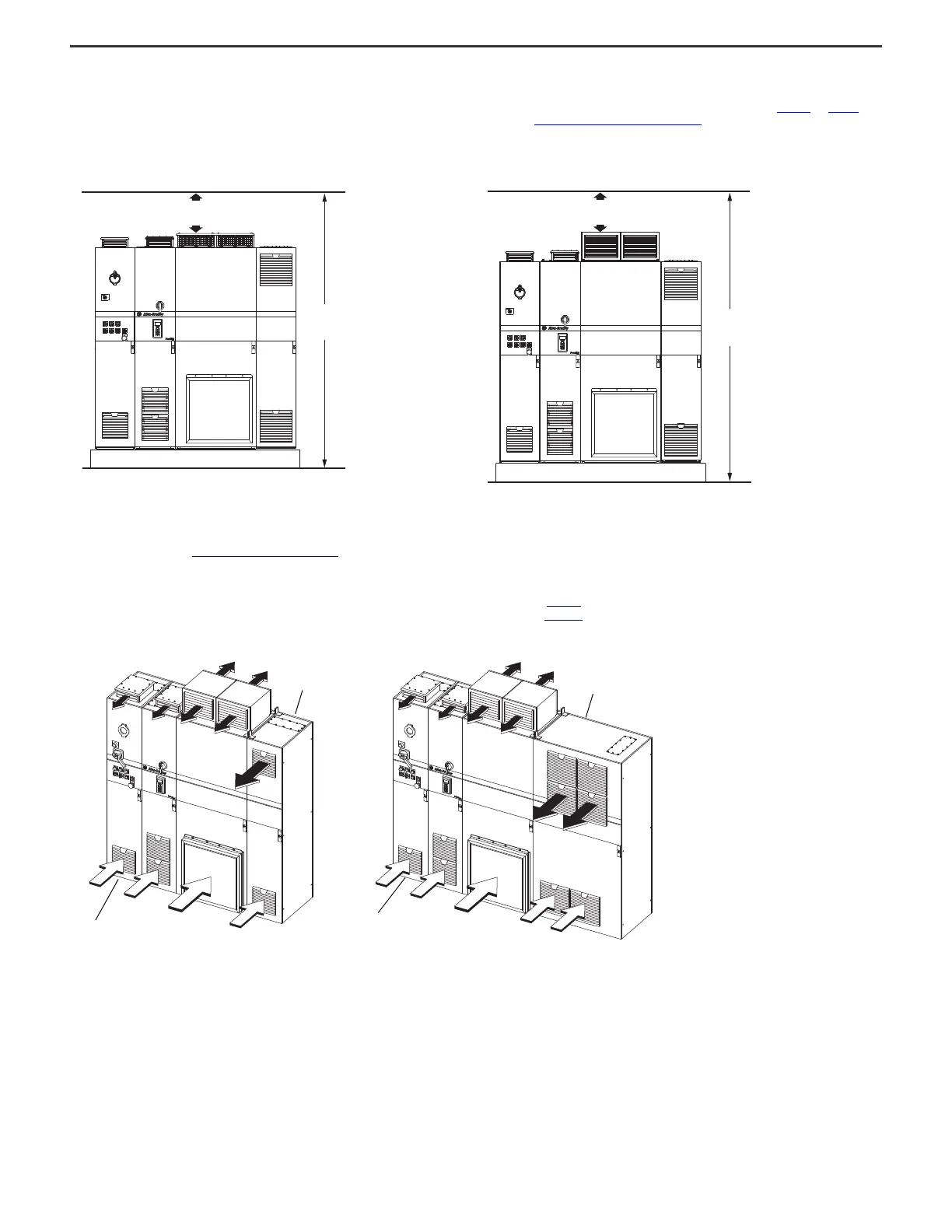
Overhead Clearance
Overhead clearance is the minimum space that is required above the bays to allow for installation and servicing of the roof exhaust vents. This clearance varies depending on which type of bay is used, IP21, UL Type 1, or
IP54, UL Type 12. The overhead clearance of the entire lineup of bays together is determined by the overhead clearance of the drive main power bay because it has the tallest roof exhaust vents. Figure 10
and Figure 11 show
the bays on 100 mm (3.9 in.) tall mounting hardware. Mounting hardware can be up to 254 mm (10.0 in.) tall. This limit is due to Service Cart Access Requirements
on page 10 and an installation limit per NEC requirements
for the height of the breaker/disconnect handle. Take the height of your mounting hardware into consideration when making sure that overhead clearance requirements are met.
Airflow Clearances and Considerations
Make sure that the air-intake and exhaust locations are not obstructed. Airflow through the bay is required to maintain proper cooling. Make sure that air temperature around the bays does not exceed the ambient
temperature specification in the Environmental Specifications
on page 5.
Some airflow examples are provided in the following figures. The vents below the center of the bay are air-intake locations (white arrows) and the vents above the center of the bay are air exhaust locations (black arrows).
Regularly inspect and replace the filter media at air-intake and exhaust locations to maintain proper airflow and cooling. For filter maintenance schedules, see the following publications:
• For configured bay filters, see the PowerFlex 755T Drives Configured to Order Program Installation Instructions, publication 750-IN118
.
• For drive bay filters, see the PowerFlex 750-Series Products with TotalFORCE Control Hardware Service Manual, publication 750-TG100
.
Figure 12 - Air-intake and Exhaust Locations: Examples Showing Frame 8 Lineups Including Configured Input Bay, Drive Bays, and Configured Output Bay
Figure 10 - Overhead Clearance for Frame 8 and 9, IP21, UL Type 1 Enclosures
(Frame 8 bays shown)
Figure 11 - Overhead Clearance for Frame 8 and 9, IP54, UL Type 12 Enclosures
(Frame 8 bays shown)
200 mm (7.9 in.)
(95.8 in.)
100 mm (3.9 in.) mounting hardware
2641 mm
250 mm (9.8 in.)
(104.0 in.)
100 mm (3.9 in.) mounting hardware
Configured input bay with input
circuit breaker, top entry
Configured input bay with input
circuit breaker, top entry
Configured output bay with
contactor only, top or
bottom exit
Configured output bay with
sine-wave filter and contactor,
top or bottom exit

 Loading...


