46 Rockwell Automation Publication 750-PC108A-EN-P - April 2021
PowerFlex 755T Drives Configured to Order Program Product Information
Terminal Lug Connections
To determine if this hardware is used with your product, see Electrical Connections Made to Each Configured Bay During Installation on page 17. Different versions of terminal lug connection hardware are used for various
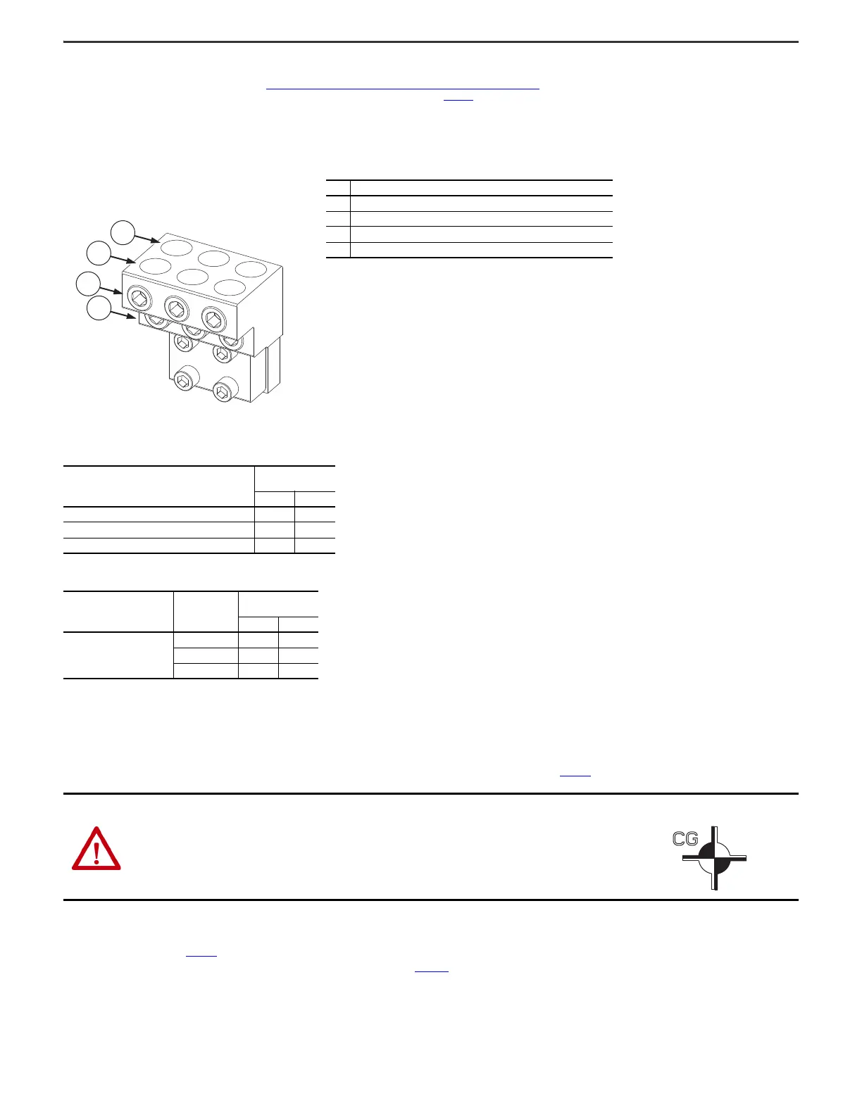
connections in some configured input bays and configured output bays. One example of a terminal lug is shown in Figure 51
. Terminal lug connection hardware varies in how many cables can be connected and what size of
cables can be connected. For details about specific terminal lug connections, see the following tables. Make a terminal lug connection as follows:
1. Strip only enough insulation off the end of the power cable for the bare cable to get all the way down the terminal to the point where it is in front of the set screw for that terminal.
2. Insert the bare cable all the way down the terminal to the point where it is in front of the set screw for that terminal.
3. Tighten the set screw for that terminal to the torque listed in one of the following tables, securing the cable.
Move the Bays
To move the bays, see the PowerFlex 755T Drives Configured to Order Program Receiving, Handling, and Storage Installation Instructions, publication 750-IN110.
Join the Bays
If your product was shipped divided into multiple shipping sections, you must join the sections together at the installation site. For instructions on joining bays see the PowerFlex 755T Drives Configured to Order Program
Installation Instructions, publication 750-IN118
.
Also see the PowerFlex 750-Series Products with TotalFORCE Control Installation Instructions, publication 750-IN100
. That publication contains procedures and precautions concerning the removal and proper handling of
components from the drive power bay when joining the drive power bay to another bay.
Figure 51 - Example Terminal Lug
Item Description
1 Back row of cable terminals, secured by bottom row of cable set screws
2 Front row of cable terminals, secured by top row of cable set screws
3 Top row of cable set screws
4 Bottom row of cable set screws
Table 10 - Frame 8 Terminal Lug Locations and Torques
Location of Terminal Lug Connection
Tightening Torque
for Set Screw
N•m lb•in
Configured input bay input protection circuit breaker 43 380
Configured input bay input protection fuse busbars 42 375
Configured output bay contactor 42 375
Table 11 - Frame 9 Terminal Lug Locations and Torques
Location of Terminal Lug
Connection
Circuit Breaker
Frame Size
(1)
(1) To find the frame size of your circuit breaker, find the catalog number
on the circuit breaker. This catalog number begins with “140G” followed
by the circuit breaker frame size, “-M”, “-N”, or “-R”. Use the
corresponding torque value.
Tightening Torque
for Set Screw
N•m lb•in
Configured input bay input
protection circuit breaker
M43380
N43380
R57505
ATTENTION: Do not move the bays in any way other than as described in the PowerFlex 755T Drives Configured to Order Program Receiving,
Handling, and Storage Installation Instructions. Moving the bays in another way can cause personal injury or damage to the equipment.
ATTENTION: For bays that have a high center of gravity, a tip-over hazard exists. To guard against death, serious personal injury, or equipment
damage, do not subject such bays to high rates of acceleration or deceleration while transporting. Do not push or pull above the center of gravity
symbol on a bay.
Figure 52 - Center of Gravity Symbol

 Loading...


