18 Rockwell Automation Publication 750-PC108A-EN-P - April 2021
PowerFlex 755T Drives Configured to Order Program Product Information
Frame 8 Electrical Connections
Frame 9 Electrical Connections
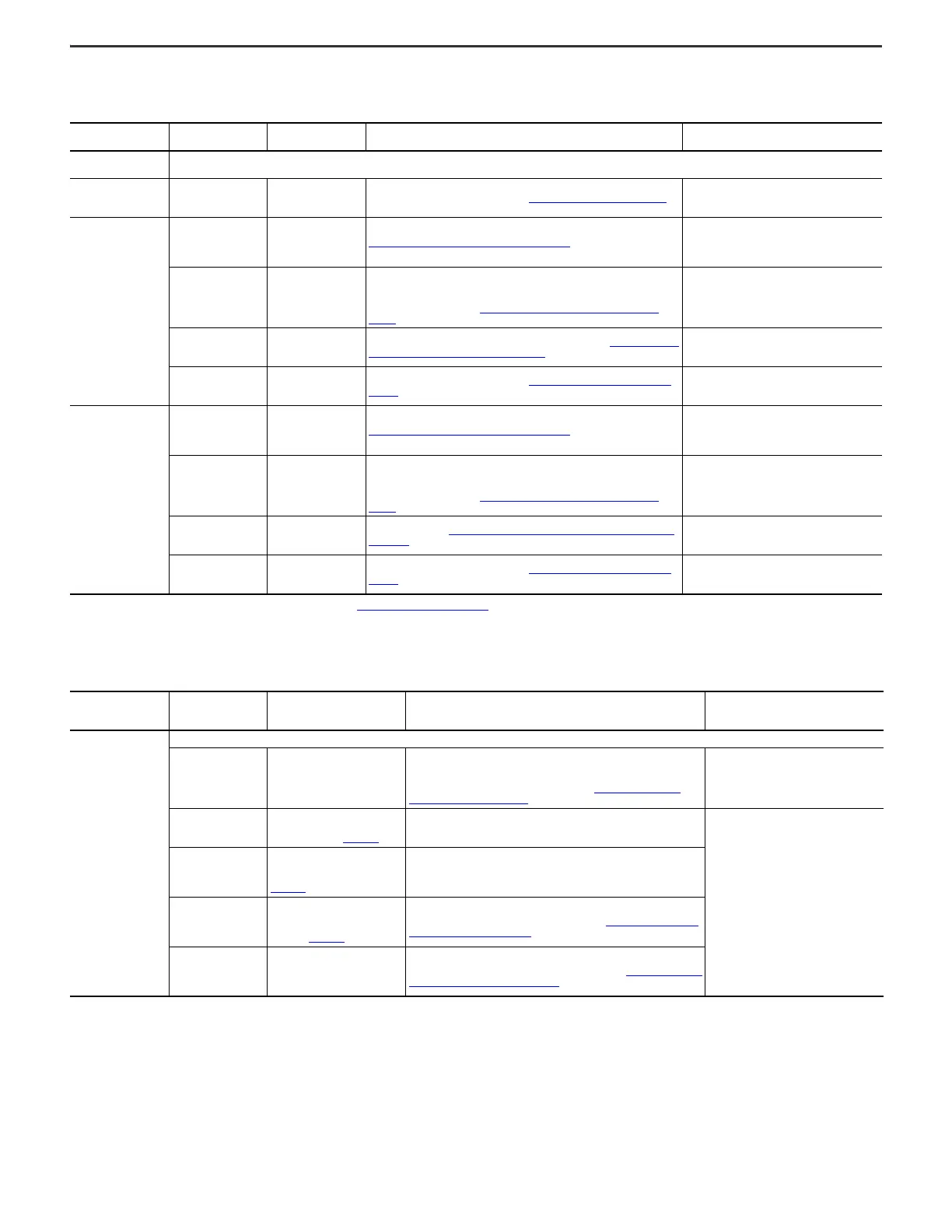
Table 7 - Frame 8 Configured Bays - Bay to Bay, Bay to Customer Power Source, and Bay to Customer Motor Electrical Connections Made During Installation
(1)
(1) Not all grounding connections included. For grounding connections, see Grounding Requirements on page 17.
Configured Bay
Connection Location
On Configured Bay
Item Connected to
Configured Bay
Hardware Used to Make Connection
When Product Arrives to Customer, Location and
State of Materials Used to Make Connection
Configured input bay,
control-only
No connections are made to the control-only configured input bay during installation. Customer AC power source and ground are connected to the drive input bay.
Configured input bays
with input protection
AC input power terminals
Customer AC power
source
Power cables, terminal lug connection. See Terminal Lug Connections
on page 46.
• Provided by the customer
• Must be connected to configured bay during
installation
Configured output bay
with contactor only, top
or bottom exit
PE ground bar
Drive power bay PE
ground bar
PE Ground Bar Splice Connection Hardware
on page 38
• Connected to the configured output bay PE
ground bar
• Must be connected to the drive power bay PE
ground bar during installation
Configured bay control
connectors in
configured output bay
Configured bay control
connectors in
configured input bay
Each configured bay control connector in the configured input bay connects to a
configured bay control connector in the configured output bay. The connection
hardware for each of these connections is a bundle of 16 AWG control cables, with
connectors on both ends. See Configured Bay Control Connection Hardware
on
page 41.
• Inside configured input bay and drive bays
• Connected to the configured input bay
• Must be connected to configured output bay
during installation
Input terminals on
contactor
Drive power bay AC
power output busbar
Power cables with barrel lugs connect to drive output busbar. See Barrel Lug to Drive
Output Busbar Connection Hardware on page 38.
• Inside the configured output bay
• Connected to the configured output bay
• Must be connected to the drive during installation
Contactor output
terminals
Customer motor
Power cables, terminal lug connection. See Terminal Lug Connection Hardware
on
page 38.
• Provided by the customer
• Must be connected to the configured output bay
during installation
Configured output bay
with sine-wave filter and
contactor, top or bottom
exit
PE ground bar Drive PE ground bar PE Ground Bar Splice Connection Hardware
on page 38
• Connected to configured output bay PE ground
bar
• Must be connected to drive power bay PE ground
bar during installation
Configured bay control
connectors in
configured output bay
Configured bay control
connectors in
configured input bay
Each configured bay control connector in the configured input bay connects to a
configured bay control connector in the configured output bay. The connection
hardware for each of these connections is a bundle of 16 AWG control cables, with
connectors on both ends. See Configured Bay Control Connection Hardware
on
page 41.
• Inside the configured input bay and drive bays
• Connected to the configured input bay
• Must be connected to configured output bay
during installation
Input terminals on sine-
wave filter reactor
Drive AC power output
busbar
Braided busbars. See Braided Busbar to Drive Output Busbar Connection Hardware
on page 39.
• Inside the configured output bay
• Connected to the configured output bay
• Must be connected to the drive during installation
Contactor output
terminals
Customer motor
Power cables, terminal lug connection. See Terminal Lug Connection Hardware
on
page 38.
• Provided by the customer
• Must be connected to the configured output bay
during installation
Table 8 - Frame 9 Configured Bays - Bay to Bay, Bay to Customer Power Source, and Bay to Customer Motor Electrical Connections Made During Installation
(1)
Configured Bay
Connection Location
On Configured Bay
Item Connected to Configured
Bay
Material Used to Make Connection
When Product Arrives to Customer,
Location and State of Materials Used to
Make Connection
Configured input bay,
control-only
No power or ground connections are made to the control-only configured input bay during installation. Customer AC power source and ground are connected to the drive input bay.
Configured bay control
connectors in
configured input bay
Configured bay control connectors
in configured output bay
Each configured bay control connector in the configured input bay connects to
a configured bay control connector in the configured output bay. The
connection hardware for each of these connections is a bundle of 16 AWG
control cables, with connectors on both ends. See Configured Bay Control
Connection Hardware on page 41.
• Inside the drive bays
• Must be connected to both the configured
input bay and configured output bay during
installation
TB1, terminal 1, +24V DC
Drive input bay TB5 (+24V DC). See
24V DC Terminal Block and Control
Bus Connections in 750-IN100
.
Control cable - 16 AWG
• Inside the configured input bay
• Connected to the configured input bay
• Must be connected to the drive input bay
during installation
TB1, terminal 5, -24V DC
Drive input bay TB5 (Common). See
the 24V DC Terminal Block and
Control Bus Connections section in
750-IN100
.
Control cable - 16 AWG
PB3 (drive disable push
button) terminals 21 and
22
In drive input bay, control pod, main
control board, TB1 (I/O terminal
block). See the Main Control Board
section in 750-IN100
.
Control cables - 16 AWG, connected to one male connector that connects to the
TB1 female connector on the main control board. See Drive Main Control Board
Connection Hardware on page 40.
Multiple connection
locations. See the
schematic for the full
list.
22-Series I/O option module inside
control pod inside drive input bay
Control cables - 16 AWG, connected to two male connectors that connect to the
female connectors on the 22-Series I/O option module. See 22-Series I/O Option
Module Connection Hardware on page 40.

 Loading...


