20 Rockwell Automation Publication 750-PC108A-EN-P - April 2021
PowerFlex 755T Drives Configured to Order Program Product Information
Component and Connection Locations
This section provides drawings of each of the configured bays. The drawings identify components and locations of electrical or control connections to customer power, other bays, or customer motor. Connections that
must be made during installation have a statement in their description that they must be made during installation.
The drawings in this section only show and identify components and connection locations on the main structure of the bays. The drawings in this section do not show or label all cables inside the bays or the connectors on
the ends of those cables. For drawings of those connectors, see Bay to Bay Connection Hardware
on page 38. Also see Connection Hardware for Customer Power Source and Motor on page 45.
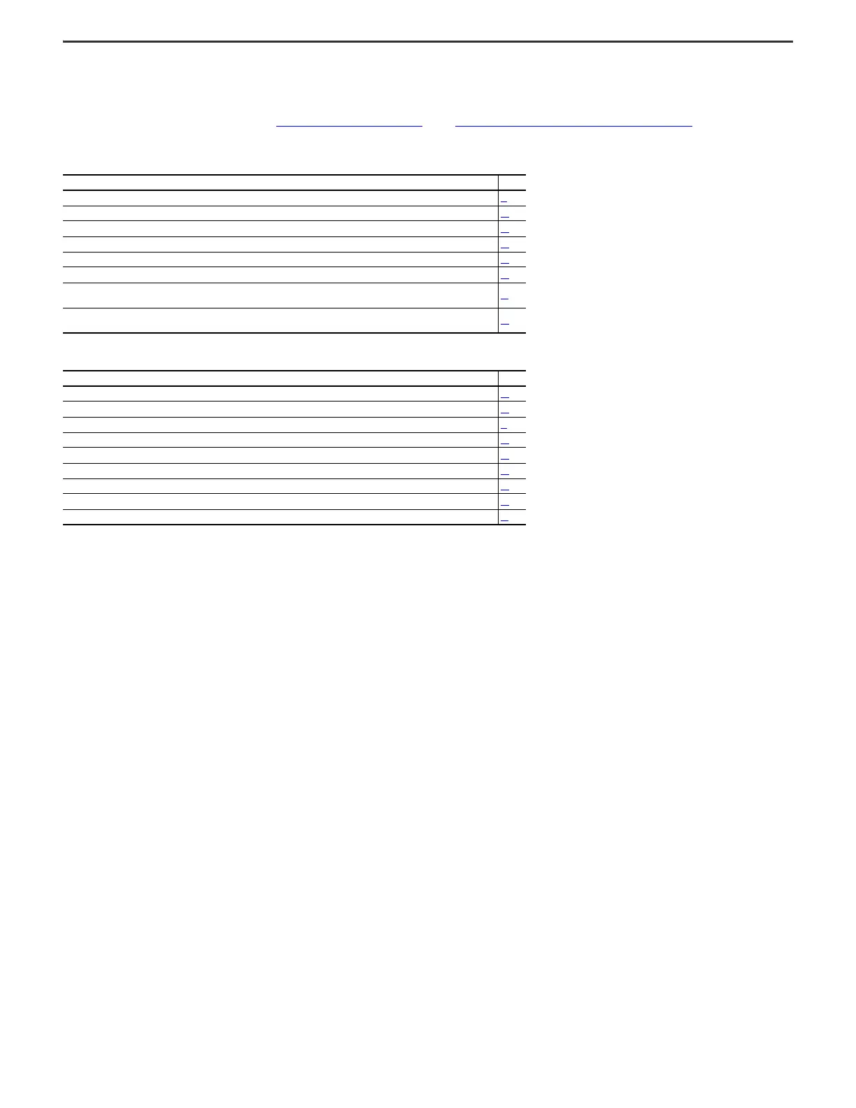
See the following tables of the figures included in this section.
Frame 8 Component and Connection Locations
Figure Page
Frame 8 All Possible Configured Input Bay Upper Door External Components 21
Frame 8 Configured Input Bay Control-only: Internal Components 22
Frame 8 Configured Input Bay with Fuses, Top Entry: Internal Components and Installation Connection Locations 23
Frame 8 Configured Input Bay with Fuses, Bottom Entry: Internal Components and Installation Connection Locations 24
Frame 8 Configured Input Bay with Circuit Breaker, Top Entry: Internal Components and Installation Connection Locations 25
Frame 8 Configured Input Bay with Circuit Breaker, Bottom Entry: Internal Components and Installation Connection Locations 26
Frame 8 Configured Output Bay with Output Contactor Only, Top or Bottom Exit: Internal Components and Installation Connection
Locations
27
Frame 8 Configured Output Bay with Sine-wave Filter and Output Contactor, Top or Bottom Exit: Internal Components and
Installation Connection Locations
28
Frame 9 Component and Connection Locations
Figure Page
Frame 9 All Possible Configured Input Bay Upper Door External Components 29
Frame 8 and 9 Configured Input Bay with Input Protection Basic Door Internal Components 30
Frame 9 Configured Input Bay Control-only: Internal Components and Installation Connection Locations 31
Frame 9 Configured Input Bay with Fuses, Top Entry: Internal Components and Installation Connection Locations 32
Frame 9 Configured Input Bay with Fuses, Bottom Entry: Internal Components and Installation Connection Locations 33
Frame 9 Configured Input Bay with Circuit Breaker, Top Entry: Internal Components and Installation Connection Locations 34
Frame 9 Configured Input Bay with Circuit Breaker, Bottom Entry: Internal Components and Installation Connection Locations 35
Frame 9 Configured Output Bay, Top Exit: Internal Components and Installation Connection Locations 36
Frame 9 Configured Output Bay, Bottom Exit: Internal Components and Installation Connection Locations 37

 Loading...


