44 Rockwell Automation Publication 750-PC108A-EN-P - April 2021
PowerFlex 755T Drives Configured to Order Program Product Information
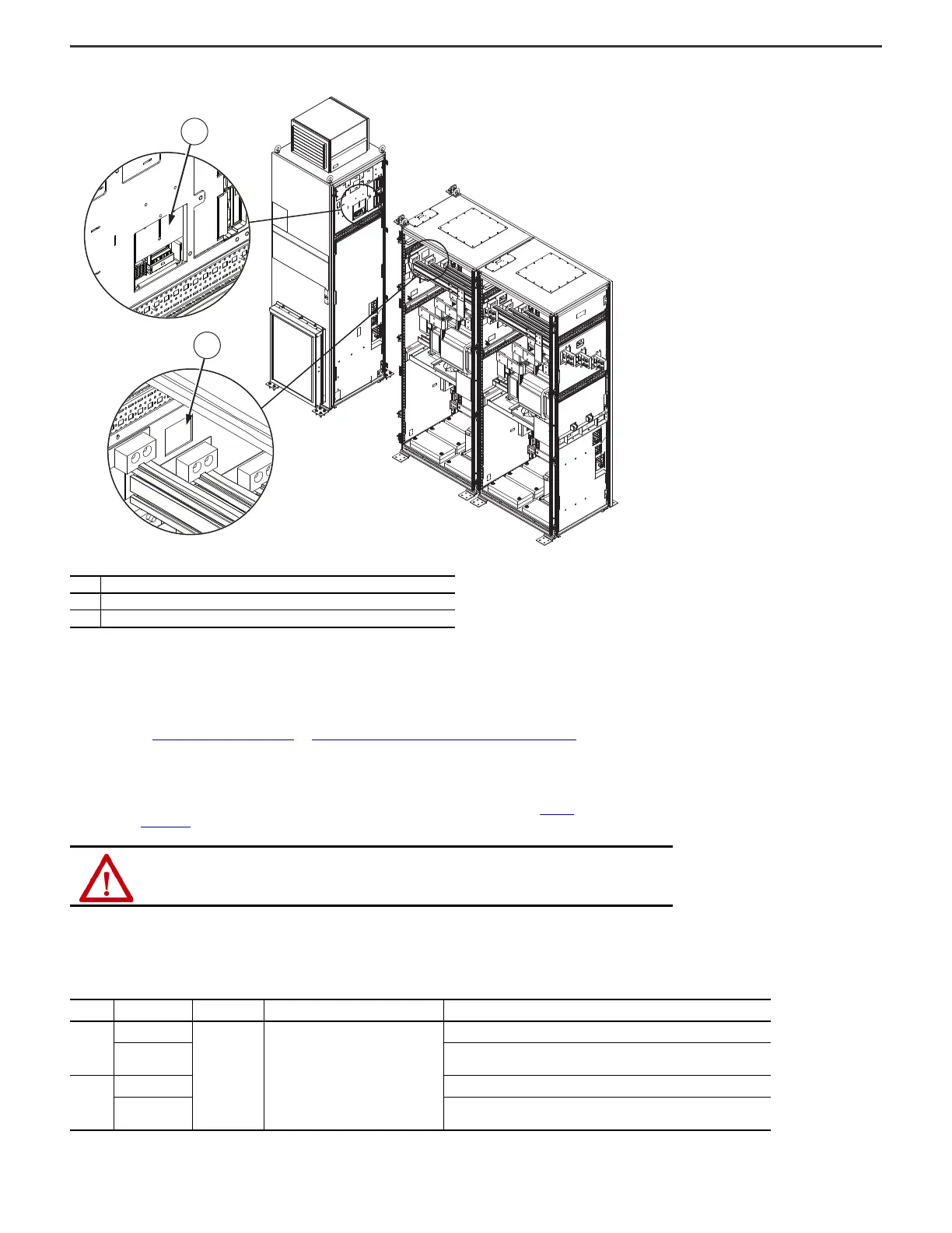
Figure 46 - Frame 9 Configured Bay Control Connector Wire Route from Drive Power Bay to Configured Output Bay
Customer Connections for AC Line Input Power and Motor Power
This section provides information about the following power connections:
• Customer supplied AC line input power connection to a configured input bay.
• Customer supplied motor connection to a configured output bay.
See the schematics that came with your product.
This section includes: Power Wiring Cable Recommendations
and Connection Hardware for Customer Power Source and Motor on page 45.
Power Wiring Cable Recommendations
This section describes the cabling recommendations for three-phase power and motor connections for the configured input and output bays. For detailed installation instructions, including cable entry and exit and
customer connection options, see the PowerFlex 755T Drives Configured to Order Program Installation Instructions, publication 750-IN118
. Also see the Wiring and Grounding Guidelines for Pulse Width Modulated (PWM) AC
Drives, publication DRIVES-IN001
, for more information on grounding.
The following recommendations apply to all input power cables for all frame sizes:
• Signal wires should be separated from power wires by at least 0.3 m (1 ft).
• The use of shielded wire for AC input power may not be necessary but is always recommended.
• The minimum insulation rating for input power wire must be at least equal to the nominal system voltage rating.
Item Description
1 Cutout for routing configured bay control wires out of the drive power bay
2 Cutout for routing configured bay control wires into the configured output bay
ATTENTION: National codes and standards (NEC, BSI, and so forth) and local codes outline provisions for safely installing electrical
equipment. Installation must comply with specifications regarding wire types, conductor sizes, branch circuit protection, and
disconnect devices. Failure to do so can result in personal injury and/or equipment damage.
Table 9 - Power Cable Recommendations
Frame Cable Use Cable Type Cable Description Minimum Insulation Rating
8
Input Power
Standard power
cable
• Three tinned copper conductors with
XLPE insulation.
• Maximum 500 MCM conductors.
• Copper braid/aluminum foil combination
shield and tinned copper drain wire, three
drain wires per cable assembly.
600V, 75 °C (167 °F)
Motor
• 400…600V systems: 600V, 75 °C (167 °F)
• 690V systems: 2000V, 90 °C (194 °F)
9
Input Power 600V, 75 °C (167 °F)
Motor
• 400…600V systems: 600V, 90 °C (194 °F), sized per 75 °C (167 °F) NEC guidelines
• 690V systems: 2000V, 90 °C (194 °F)

 Loading...


