Rockwell Automation Publication 750-PC108A-EN-P - April 2021 41
PowerFlex 755T Drives Configured to Order Program Product Information
Configured Bay Control Connection Hardware
Configured bay control connectors are used for control connections between a configured input bay and configured output bay, so they are only present in bay lineups that contain both a configured input bay and a
configured output bay. There are two configured bay control connections for each configured input bay/configured output bay pair:
• The 24V DC configured bay control connector in the configured input bay connects to the 24V DC configured bay control connector in the configured output bay.
• The 120V AC configured bay control connector in the configured input bay connects to the 120 AC configured bay control connector in the configured output bay.
The connection hardware for each of these connections is a bundle of 16 AWG control cables, with connectors on both ends. The following figures show configured bay control connectors in various types of bays.
Configured bay control connectors are located inside the bay on the side that contacts the drive, near the top of the bay. When the bays arrive to the customer, the cables for the connection are inside the shipping section
that includes the drive bays. During installation, the connectors on the ends of the cables must be connected to their corresponding configured bay control connector in the configured input bay and configured output bay.
If the configured input bay was shipped attached to the drive, its configured bay control connections are made at the factory. The configured bay control connection wires are routed into the configured bays through a
cutout below the connectors. See Figure 46 on page 44
for an example.
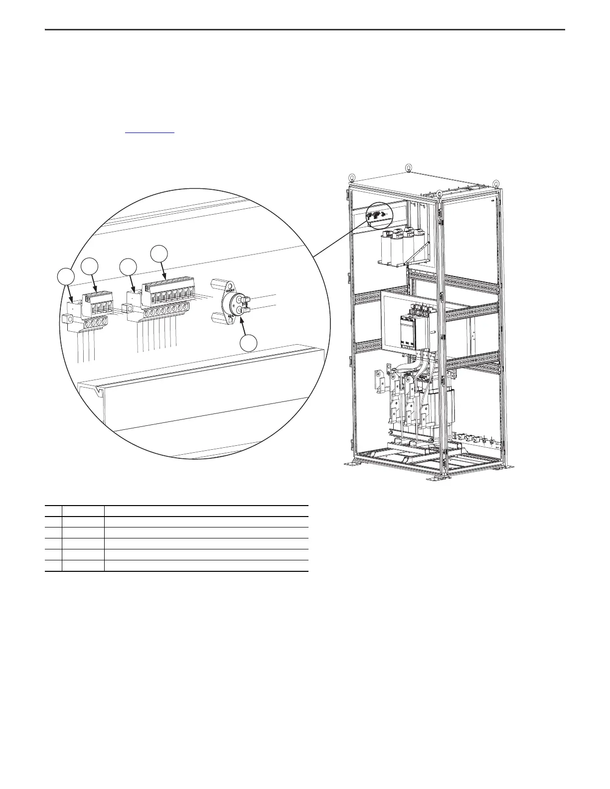
Figure 43 - Configured Bay Control Connections and Thermostat on the Frame 8 Configured Output Bay Control Panel
Item Identification Description
1 PLUG1 Four-pole female connector 24V DC
2 PLUG1 Four-pole male connector 24V DC. Must connect to item 1 during installation.
3 PLUG2 Eight-pole male connector 120V AC
4 PLUG2 Eight-pole female connector 120V AC. Must connect to item 3 during installation.
5TAS2 Thermostat

 Loading...


