42 Rockwell Automation Publication 750-PC108A-EN-P - April 2021
PowerFlex 755T Drives Configured to Order Program Product Information
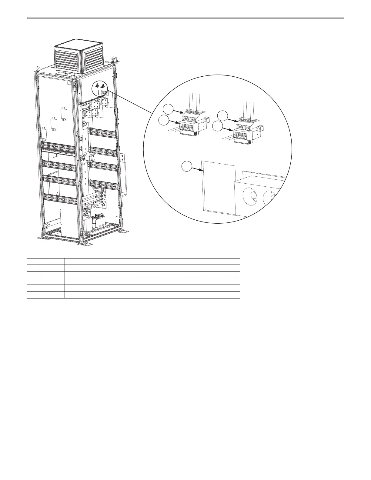
Figure 44 - Configured Bay Control Connections on the Frame 9 Configured Input Bay
Item Identification Description
1PLUG2 Four-pole female connector 120V AC
2 PLUG2 Four-pole male connector 120V AC. Must connect to item 1 during installation.
3 — Cutout for configured bay control connector wires to route between the configured input bay and the drive input bay
4 PLUG1 Four-pole male connector 24V DC. Must connect to item 5 during installation.
5 PLUG1 Four-pole female connector 24V DC

 Loading...


