Rockwell Automation Publication 750-PC108A-EN-P - April 2021 37
PowerFlex 755T Drives Configured to Order Program Product Information
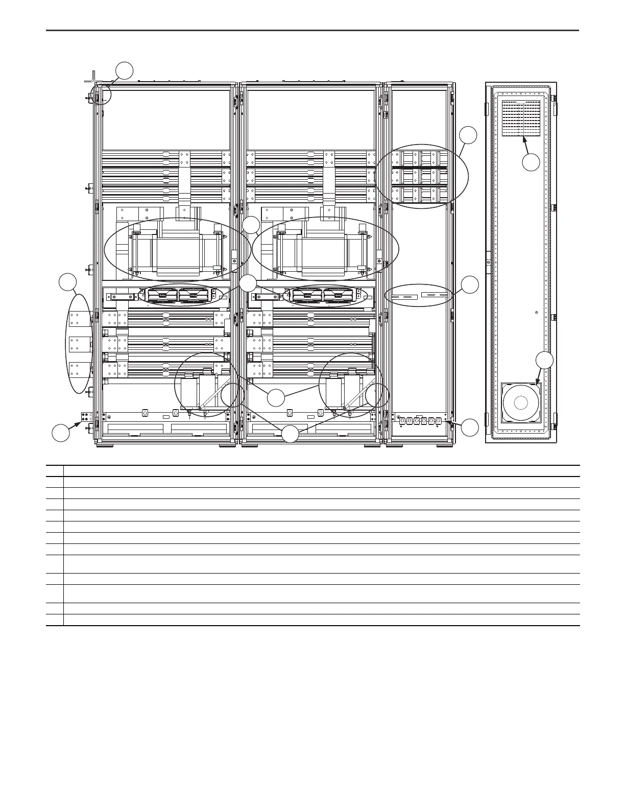
Figure 34 - Frame 9 Configured Output Bay, Bottom Exit: Internal Components and Installation Connection Locations
Item Description
1 Configured bay control connectors for control connections to configured input bay (not visible in this view, located behind bay frame). Connections must be made during installation.
2 AC busbar splice connection hardware for power from the drive
3 PE ground bar splice connection hardware. Ground splice connection to drive PE ground bar must be made during installation.
4 Thermostat (not visible in this view, located behind sine-wave filter capacitor bank)
5 Sine-wave filter capacitor bank
6 Fan for airflow upward through the bay
7 Sine-wave filter reactor
8
Connections for power output to customer motor. Connected via lug to L-bracket to extruded busbar connection. Each extruded busbar in the wire exit bay has two 4-hole L-brackets. Connections must be made
during installation.
9 Cable support brackets - support customer motor cables
10
PE ground bar with ground clamps included. The terminating point to the chassis ground for the motor and motor cable shield is the PE ground bar section in farthest right bay (the wire exit bay). Ground
connections must be made during installation.
11 Fan with internal air filter
12 Vent with internal air filter
Wire Exit Bay Door Interior

 Loading...


