Home
Alpitronic
Battery Charger
hypercharge HYC 50
Alpitronic hypercharge HYC 50 User Manual
5
of 1
of 1 rating
76 pages
Give review
Manual
Specs
To Next Page
To Next Page
To Previous Page
To Previous Page
Loading...
HYC_50
–
Operation and Installation Guide
Hardware
Version 1-2
Page
62
of
76
6.4
Procedure for error messages
All
rights
reserved.
Reproduction
of
this d
ocument,
in
whole o
r
in par
t,
is only
permitted
with
the pe
rmissio
n
of alpitroni
c
Gm
bH
.
6.4
Procedu
re for error
messages
6.4.1
Authentication failed
Figure
35
:
Authentication failed
If this error message
appears, try the authenticati
on process again.
61
63
Table of Contents
Table of Contents
6
Content
6
Figures
8
Tables
9
Safety Instructions
11
Intended Use
11
User
11
Safety Instructions for Installation and Maintenance
12
Product Description
14
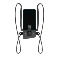
Figure 1: HYC_50 with Open Front Door (Example with Two DC Charging Cables)
14
Table 1: Overview DC Power and Options HYC_50
14
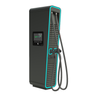
Figure 2: HYC_50 with Two DC Charging Cables
15
Charging Interfaces
16
Table 2: Charging Interfaces
16
Table 3: Possible Combinations of Charging Interfaces
16
DC-Power Unit / Power Outputs
17
Figure 3: DC Power Characteristics in Different Configurations
17
Type Plate
18
Figure 4: Example of a Type of Plate Without Calibration Conformity for HYC_50
18
Exterior View
19
Figure 5: Elements of the HYC_50
19
Opening the HYC_50
20
Figure 6: Locking Lid of the HYC_50
20
Figure 7: Front Door Locking Mechanism
20
Door Contactor
21
Interior View
22
Figure 8: Interior View of the HYC_50
22
Figure 9: Interior View Front HYC_50 (Backside)
23
Table 4: Components of the HYC_50
24
Additional Options
25
Colors HYC_50
25
Credit Card Terminal
25
Figure 10: Contactless Credit Card Terminal (Model COR A20)
25
Packaging, Transport, and Storage
26
Packaging
26
Transport, Handling, and Storage
26
Unpacking the HYC_50
26
Figure 11: Packed HYC_50
26
HYC_50 Installation and Commissioning
27
Mechanical Installation of the HYC_50
27
Mounting the Stand
27
Charging Cable Lengths
28
Figure 12: Mounting the Stand HYC_50
28
Figure 13: Cable Length for the Two DC Outputs of the HYC_50 with Cable Management
28
Location Selection
29
Figure 14: Recommended Minimum Distances for Site Selection
29
Figure 15: Installation Height (Barrier-Free) and Minimum Distances for Supply Air and Exhaust
30
Positioning of Mounting Frame HYC_50
31
Mounting the HYC_50
32
Mounting Preparation
32
Figure 16: Cable Gland
32
Table 5: Load Table for Fischer Dowels/Anchors
32
Figure 17: Strain Relief for Different Cable Diameters
33
Installation of the Connection Cable in the Cable Inlet
34
Table 6: Assembly Steps HYC_60
38
Electrical Installation
39
Circuit Diagram HYC_50
40
Figure 18: Circuit Diagram of the HYC_50
40
Connecting the Mains Cables
41
Table 7: Recommended Cross-Sections
41
Surge Protection
42
Checks before Switching on for the First Time
42
Table 8: Checks before Commissioning
42
Commissioning Protocol
43
Diagnosis and Parameterization
46
Table 9: Default IP Address of the HYC_50
46
Operation of the HYC_50
47
Starting the Charging Process
47
Authentication
47
Figure 19: Authentication
47
Figure 20: Overview of the Authentication Options
48
Figure 21: Authentication Process
49
Figure 22: Overview User Guide Per Authentication Option
50
Charging Plug Selection
51
Figure 23: Charging Plug Selection
51
Figure 24: Language Selection
52
Plugging in the Charging Cable
53
Figure 25: Plugging in the Charging Cable
53
During the Charging Process
54
Charging Overview
54
Figure 26: Initializing
54
Figure 27: Overview of Charging Process
55
Figure 28: Detailed Loading Overview
56
Figure 29: Load Second Vehicle
57
Stop Charging Process
58
Wake Screen
58
Stop Charging
58
Figure 30: Charging Overview with Two Active Charging Processes
58
Figure 31: Stop Charging
59
Figure 32: Authentication to Stop Charging Process
60
Figure 33: Process Charging Stop
60
Figure 34: Unplug the Charging Connector
61
Procedure for Error Messages
62
Authentication Failed
62
Figure 35: Authentication Failed
62
Charging Plug Defective
63
Figure 36: Charging Plug Defective
63
Error During Communication Setup
64
Figure 37: Error During Communication Setup
64
Connector Locking Failed
65
Figure 38: Connector Locking Failed
65
The Vehicle Signals an Error
66
Figure 39: Vehicle Error
66
Fault Description and Correction
67
Table 10: Fault Description and Correction
67
Maintenance
68
Overview of the Maintenance Work
68
Function Test of the Main Switch
68
Table 11: Regular Maintenance Work
68
Review of the Protective Measures
69
Figure 40: Main Switch with Connected Cables
69
Figure 41: Digital Multimeter for Voltage Free Testing
69
Checking Cleanliness and Condensation
70
Checking the Screws
70
Replacing the Air Filter Inserts
70
Figure 42: Air Filter Inlet
70
Table 12: Torque of Components
70
Plug Contacts Charging Cable Set
71
Figure 43: Air Filter Outlet
71
Figure 44: Charging Plug Side View
71
Check Overvoltage Protection
72
Figure 45: Charging Plug Contactors
72
Figure 46: Check of Overvoltage Protection
72
Repair and Service
73
Disposal
74
Technical Data
75
Table 13: Technical Data
75
Table 14: Mechanical Data
75
Table 15: Electrical Connection Data HYC_50
75
Table 16: Idle Power Dissipation at 400V According to the Display Brightness
76
Table 17: Frequency Bands and Transmission Levels of the HYC_50
76
5
Based on 1 rating
Ask a question
Give review
Questions and Answers:
Need help?
Do you have a question about the Alpitronic hypercharge HYC 50 and is the answer not in the manual?
Ask a question
Alpitronic hypercharge HYC 50 Specifications
General
Brand
Alpitronic
Model
hypercharge HYC 50
Category
Battery Charger
Language
English
Related product manuals
Alpitronic Hypercharger HYC 50
76 pages
Alpitronic Hypercharger HYC 150
105 pages
Alpitronic Hypercharger HYC 300
105 pages
 Loading...