All rights reserved. Reproduction of this document, in whole or in part, is only permitted with the permission of alpitronic GmbH.
Figures
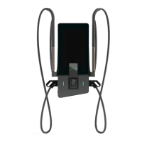
Figure 1: HYC_50 with open front door (Example with two DC charging cables) ..............14
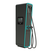
Figure 2: HYC_50 with two DC charging cables ................................................................15
Figure 3: DC power characteristics in different configurations ...........................................17
Figure 4: Example of a type of plate without calibration conformity for HYC_50 ................18
Figure 5: Elements of the HYC_50 ....................................................................................19
Figure 6: Locking lid of the HYC_50 ..................................................................................20
Figure 7: Front door locking mechanism ...........................................................................20
Figure 8: Interior view of the HYC_50 ...............................................................................22
Figure 9: Interior view front HYC_50 (Backside) ...............................................................23
Figure 10: Contactless credit card terminal (model COR A20) ..........................................25
Figure 11: Packed HYC_50 ..............................................................................................26
Figure 12: Mounting the Stand HYC_50 ...........................................................................28
Figure 13: Cable length for the two DC outputs of the HYC_50 with cable management ..28
Figure 14: Recommended minimum distances for site selection .......................................29
Figure 15: Installation height (barrier-free) and minimum distances for supply air and exhaust
air .....................................................................................................................................30
Figure 16: Cable gland ......................................................................................................32
Figure 17: Strain relief for different cable diameters ..........................................................33
Figure 18: Circuit diagram of the HYC_50 .........................................................................40
Figure 19: Authentication ..................................................................................................47
Figure 20: Overview of the authentication options .............................................................48
Figure 21: Authentication process .....................................................................................49
Figure 22: Overview user guide per authentication option .................................................50
Figure 23: Charging plug selection ....................................................................................51
Figure 24: Language selection ..........................................................................................52
Figure 25: Plugging in the charging cable .........................................................................53
Figure 26: Initializing .........................................................................................................54
Figure 27: Overview of charging process ..........................................................................55
Figure 28: Detailed loading overview ................................................................................56
Figure 29: Load second vehicle ........................................................................................57
Figure 30: Charging overview with two active charging processes ....................................58
Figure 31: Stop charging ...................................................................................................59
Figure 32: Authentication to stop charging process ...........................................................60
Figure 33: Process charging stop......................................................................................60
Figure 34: Unplug the charging connector ........................................................................61
Figure 35: Authentication failed .........................................................................................62
Figure 36: Charging plug defective ...................................................................................63
Figure 37: Error during communication setup ...................................................................64
Figure 38: Connector locking failed ...................................................................................65
Figure 39: Vehicle error ....................................................................................................66
Figure 40: Main switch with connected cables ..................................................................69
Figure 41: Digital multimeter for voltage free testing .........................................................69
Figure 42: Air filter inlet .....................................................................................................70
Figure 43: Air filter outlet ...................................................................................................71
Figure 44: Charging plug side view ...................................................................................71
Figure 45: Charging plug contactors .................................................................................72
Figure 46: Check of overvoltage protection .......................................................................72
 Loading...