Enova DGX DXLink™ Twisted Pair 4K Boards
105
Hardware Reference Manual – Enova DGX 100 Series Digital Media Switchers
Important DXLink Twisted Pair 4K Cabling Requirements and Recommendations
The following requirements and recommendations apply to cabling DXLink (RJ-45) connectors:
DXLink cable runs require shielded category cable (STP) of Cat6A or Cat7.
DXLink cable runs for DXLink equipment shall only be run within a common building.**
DXLink delivers 10.2 Gb/s throughput over shielded category cable. Based on this bandwidth requirement, we recommend
following industry standard practices designed for 10 Gigabit Ethernet when designing and installing the cable
infrastructure.
The cables should be no longer than necessary to reach the end-points. We recommend terminating the cable to the actual
distance required rather than leaving any excess cable in a service loop.
For complete cable specifications, see the board’s specifications.
** “Common building” is defined as: Where the walls of the structure(s) are physically connected and the structure(s) share a
single ground reference.
For more details and helpful cabling information, reference the white paper titled “Cabling for Success with DXLink” available at
www.amx.com or contact your AMX representative.
NOTE: DXLink Twisted Pair 4K cable runs include support for up to two (2) patch cables of up to 5 meters in length each, provided
that the total end-to-end cable length does not exceed 80 meters and all cables and couplers/patch panels used in the run meet the
minimum cable requirements (e.g., from DX-TX-DWP-4K to 5m patch cable, 70m cable run, 5m patch cable to DXLink 4K Input Board
using shielded Cat6A or better for each cable length).
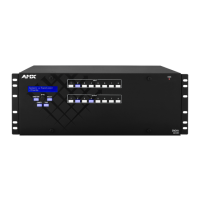
Twisted Pair Cable Pinouts
Use either the T568A or T568B pinout specification for termination of the twisted pair cable used between the Transmitter or
Receiver and the enclosure.
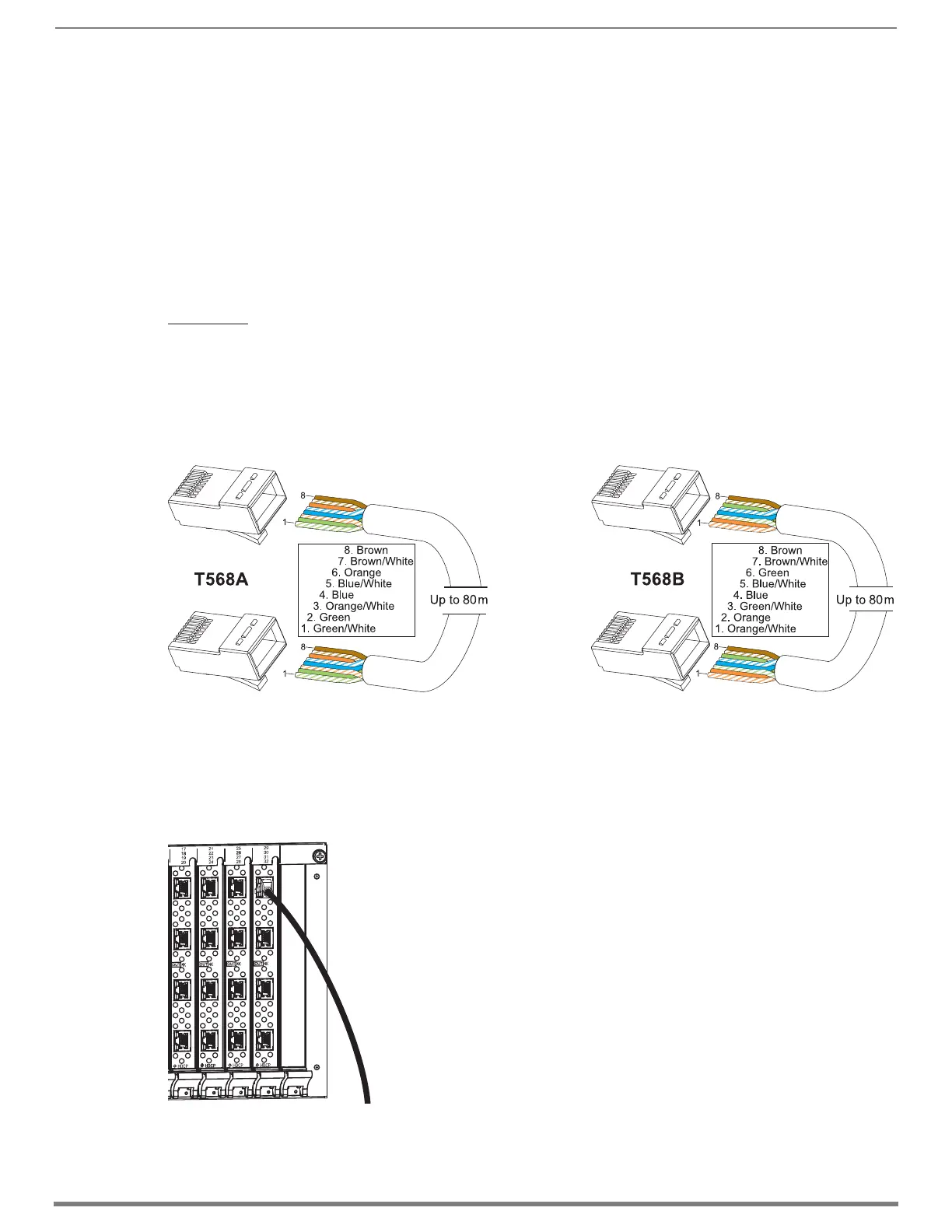
To connect sources and destinations to DXLink inputs and outputs via TX/RX:
1. Attach an HDMI cable from the source device to the HDMI connector on the DXLink Transmitter.
2. Attach a twisted pair cable to the DXLink Transmitter’s Output (RJ-45) connector.
3. Attach the other end of the twisted pair cable to the input connector on the DXLink Input Board.
4. Attach a second twisted pair cable to the output connector on the DXLink Output Board.
FIG. 55 Twisted pair cable pinouts for T568A and T568B
FIG. 56 Fasten cables onto input and output connectors
 Loading...