Switching, Configuration, and Status
177
Hardware Reference Manual – Enova DGX 100 Series Digital Media Switchers
Status Page
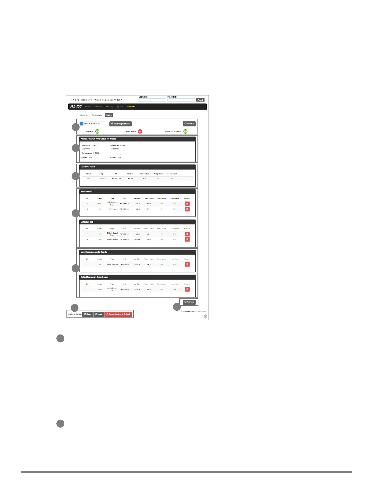
The Status page is used to check a number of the switcher’s components and their states. The components (from top to bottom of
page) display status for Alarms, the Chassis, the Master CPU Board, Input and Output Boards, and Input and Output Expansion
Audio Boards. A quick glance at this page will indicate whether the system is running okay (green text will state OK) or if any thing
is failing (red text will state FAIL.)
IMPORTANT: The Status page settings are not asynchronous. To obtain the latest information, the Refresh button must be clicked.
The example provided in the figure below is based on an Enova DGX 3200 Switcher with two each standard Input and Output
Boards, as well as two Expansion Audio Boards.
System Auto-Setup check box – select to place the system in auto-setup mode (i.e., the mode wherein the system requires only a
single IP address for the integrated Master, and each endpoint is automatically configured for communication via a private LAN
hosted by the integrated Master).
The following must be adhered to when using auto-setup mode (default):
□ Endpoints must be set to DHCP Mode (default)
□ Endpoints must use NDP Master connection mode (default)
□ Endpoints must not be currently bound (traditional NetLinx binding) to a Master
□ Endpoints DIP switch setting for Toggle #3 (network connectivity) is ignored while in auto-setup mode
NOTE: Some devices run on a secured file-system. As such, file-system operations (e.g., Load and Save operations) may not be
supported by the device’s default capabilities and may require downloading a file manager application.
Alarms – if any are red, consult the individual Fan, Power, and Temperature components on the page to help pinpoint the problem.
Refresh button – if necessary, use the Refresh button to view system status changes.
Chassis field – this field contains readouts for individual fan speeds, individual power supply status, and the current temperature of
the chassis (shown in degrees Celsius). Each readout displays in a color to convey statuses of OK, Fail, or no problems detected
(black). Fan speed information is displayed by individual fans (Fan #) and the fan assembly where each fan is located (FAN ASM #).
Power supply and temperature information is available in each switcher’s General Specifications table in the “Product Overview and
General Specifications” chapter.
FIG. 108
Status page indicates status of system components
E
D
C
B
A
F
G
A
B
 Loading...