1. Open the condensate sample valve at the side of the compressor (drain plate) for 5 seconds and dispose
of the collected condensate according to local regulations for oil containing water. (This is to remove the
water that remains in the test outlet tube between the OSCi and the compressor back panel).
2. Re-open the test valve and collect the condensate in the test bottle.
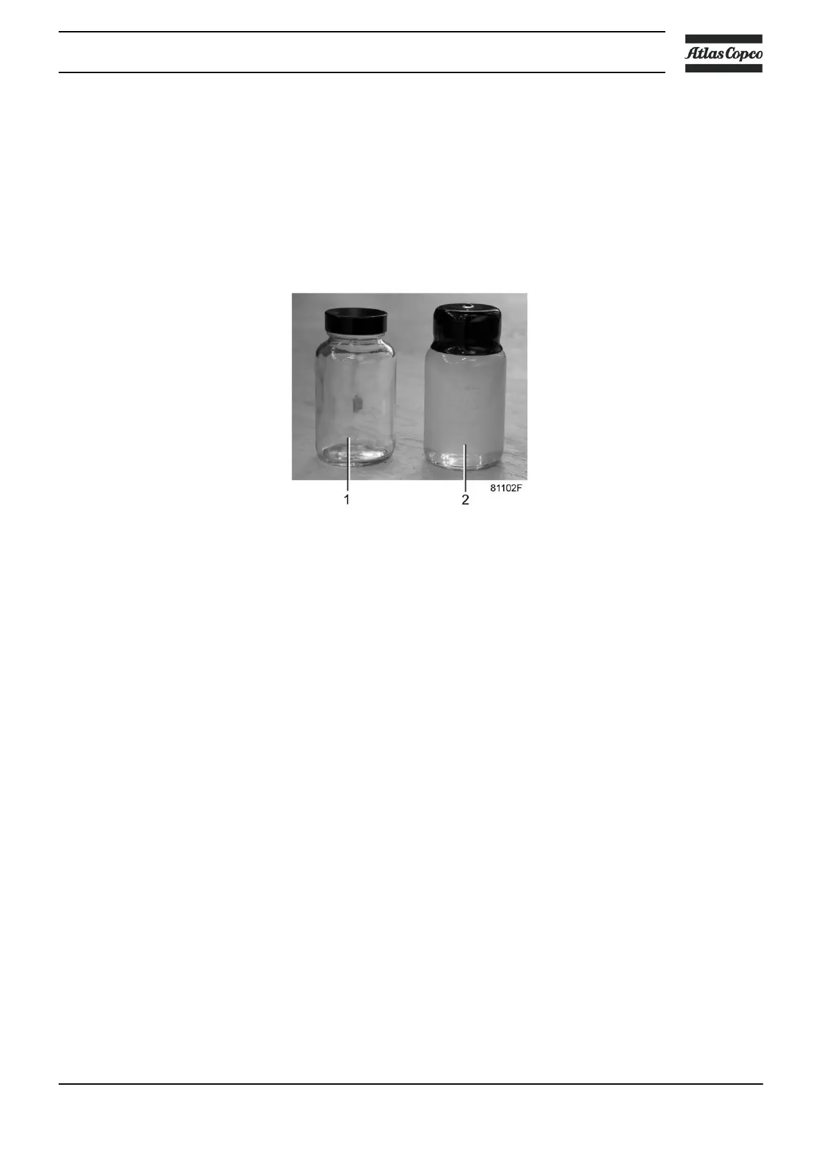
3. Compare the turbidity of the sample with the 15 ppm turbidity reference bottle.
4. If the turbidity of the test sample is more intense than the reference turbidity, a request for servicing should
be initiated, to be carried out within 2 weeks time. The vertical position of the test outlet ensures that there
is enough clean activated carbon left above this position to keep the condensate under 15 ppm for at least
2 weeks (valid for a GA 90 with dryer which runs 24 h/day at reference conditions).
Test/sample bottle (1) and turbidity reference bottle (2)
Oleophilic filter
Initially, the oleophilic filter (3 - Condensate flow scheme) will float almost completely on the condensate
and only the bottom part will act as filtration medium. By sorbing more and more oil, the filter will sink and
new filter material will be exposed to the condensate. When the top of the filter reaches the surface of the
condensate in the first vessel, the filter is saturated and needs to be replaced. This is automatically transmitted
to the Elektronikon® regulator via the level sensor (1 - View of OSCi inlet), but the customer can also check
this visually through the sight-glass.
Filter replacement instructions
This instruction makes clear which steps have to be taken to do maintenance and to ensure proper functioning
after maintenance. These are the steps to be taken when servicing:
1. Stop the compressor and close the air outlet valve. Switch off the voltage.
2. Open/ remove the compressor side panel in front of the OSCi.
3. Position the drain tubes connected to the service drain valves (4 - Condensate flow scheme and View of
OSCi) over a recipient and open the drain valves. Wait until the drains are fully discharged and dispose
of the oil-containing water according to local regulations.
4. Unscrew the bolts that fix the OSCi to the compressor floor plate and detach the tubes and wires from
vessel 2. The OSCi can then be taken out of the compressor. The attached tubes and electrical wires are
long enough to slide out the OSCi without disconnecting them, but this should be done carefully, paying
attention not to obstruct the tubes and wires.
5. Unscrew the clamping rings, take off the covers and take out the 3 filter bags. The buckets in which the
new filters are supplied can be used to store the old filters.
Instruction book
2920 7109 60 133

 Loading...


