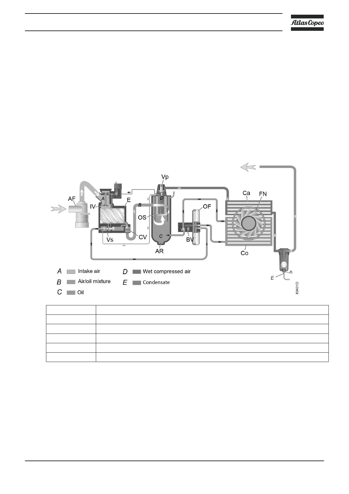
Air pressure forces the oil from air receiver/oil separator (AR) through oil filter (OF) and oil stop valve (Vs)
to compressor element (E).
Bypass valve (BV) starts opening the supply from cooler (Co) when the oil temperature has increased to the
set point. At approx. 15 ˚C (27 ˚F) above the set point, all the oil flows through the oil cooler.
Oil stop valve (Vs) prevents the compressor element from flooding with oil when the compressor is stopped.
The valve is opened by element outlet pressure when the compressor is started.
2.4 Cooling system
Air-cooled compressors
References Description
A Intake air
B Air/oil mixture
C Oil
D Wet compressed air
E Condensate
Description
The cooling system on air-cooled compressors comprises air cooler (Ca) and oil cooler (Co).
The cooling air flow is generated by fan (FN).
Instruction book
2920 7109 60 19