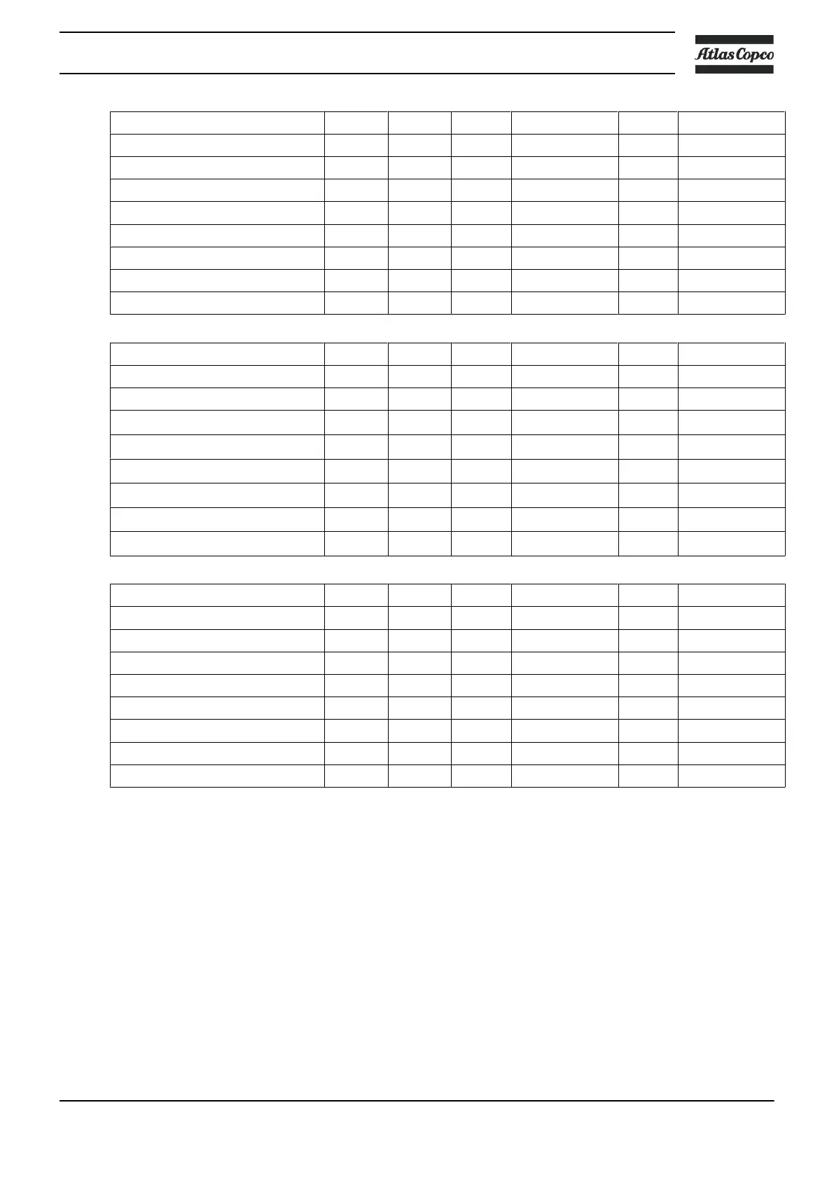
Compressor type I (1) Max. fuse (1) I (2) Max. fuse (2)
gL/gG gL/gG
V Hz A A A A
GA 75 200 50 329 400 346 400
GA 75 400 50 160 200 168 200
GA 75 200 60 311 355 329 400
GA 75 230 60 269 300 285 315
GA 75 380 60 163 200 172 200
GA 75 460 60 134 160 142 160
Compressor type I (1) Max. fuse (1) I (2) Max. fuse (2)
gL/gG gL/gG
V Hz A A A A
GA 75
+
200 50 309 355 326 400
GA 75
+
400 50 155 200 162 200
GA 75
+
200 60 311 355 329 400
GA 75
+
230 60 269 315 285 315
GA 75
+
380 60 163 200 172 200
GA 75
+
460 60 134 160 142 160
Compressor type I (1) Max. fuse (1) I (2) Max. fuse (2)
gL/gG gL/gG
V Hz A A A A
GA 90 200 50 390 500 407 500
GA 90 400 50 194 224 202 224
GA 90 200 60 370 400 388 425
GA 90 230 60 326 400 342 400
GA 90 380 60 198 250 208 250
GA 90 460 60 162 200 169 200
I: current in the supply lines at maximum load and nominal voltage
(1): compressors without integrated dryer
(2): compressors with integrated dryer
Fuse calculations for IEC are done according to 60364-4-43 electrical installations of buildings, part 4:
protection for safety- section 43: protection against overcurrent. Fuse sizes are calculated in order to protect
the cable against short circuit.
Possible configurations
There are 3 possible cabling layouts:
Instruction book
2920 7109 60 189

 Loading...


