Survivable Branch Appliance
AudioCodes Enhanced Media Gateway 32 Document #: LTRT-18206
2.2.3 Cabling the Standard Interfaces
This section describes the cabling of the device.
Electrical Earthing
The device must be permanently connected to the earth using the screw provided
on the rear panel. Use 14-16 AWG wire and a proper ring terminal for the earthing.
¾ To cable the device:
1. Permanently earth (ground) the device (refer to 'Earthing (Grounding) the Device' on page
33).
2. Connect the E1/T1 trunk interfaces (refer to 'Connecting the E1/T1 Trunk Interfaces' on page
33).
3. Connect the Ethernet interface (refer to 'Connecting the Ethernet Interface' on page 34).
4. Con
nect the power supply (refer to 'Connecting to the Power Supply' on page 34).
Once you ha
ve completed the above hardware installation steps, after powering-up the device
the Ready and LAN LEDs on the front panel turn green (after a self-testing period of about three
minutes). Any malfunction changes the Ready LED to red.
The cabling method of the device (performed on the rear panel), depends on the number of
supported trunks (and power socket type):
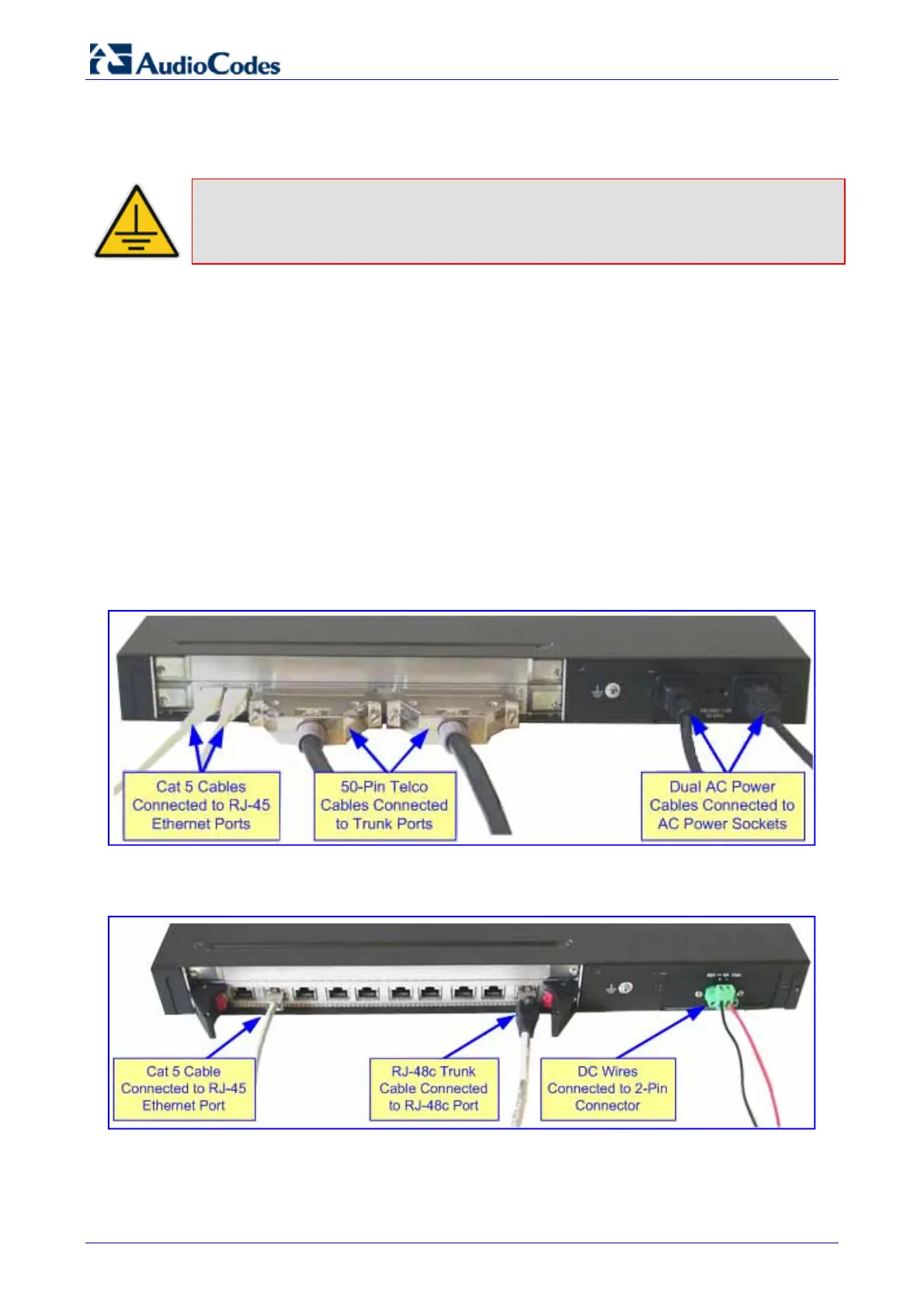
Cabling for 16 trunks and dual AC power:
Figure 2-21: Rear-Panel Cabling for 16 Trunks (Dual AC)
Cabling for eight trunks and DC power:
Figure 2-22: Rear-Panel Cabling for 8 Trunks (DC Power)

 Loading...


