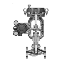
(5) Mounting the upper diaphragm case
Step Procedure
1 Set the upper diaphragm case such that the air pipe connection port is in the position
indicated in
Figure 6-7 to Figure 6-10 (for direct operation models) or the air vent
hole is in the position indicated in
Figure 6-11 to Figure 6-14 (for reverse opera-
tion models). Check that the matching marks that were made before disassembly are
aligned.
2 Tighten the eyebolts alternately and evenly.
3 Secure the upper and lower diaphragm case using hex nuts.
4 Tighten the nuts evenly in a diagonal pattern with the tightening torque indicated in
Table 6-1.
5 For reverse operation actuators, screw the waterproof cap onto the air vent hole of the
upper diaphragm case.
CAUTION
For an actuator that incorporates springs, be sure to follow the
assembly procedure when attaching bolts and nuts. Otherwise,
malfunction may result.
(6) Inspection after reassembly
Step Procedure
1 Apply air at a pressure of 490 kPa to the diaphragm case through the air pipe connec-
tion port of the case. Using soapy water, check the exterior of the diaphragm case (for
direct operation models) or the exterior of the rod (for reverse operation models) for air
leakage.
2 Change the air pressure within the supply air pressure specified for the actuator to check
that the valve moves smoothly for all openings, and that the spring range for a valve
opening is the same as the range printed on the nameplate.
6-11

 Loading...