3. Physical installation
1
2
3
4
7
8
5
6
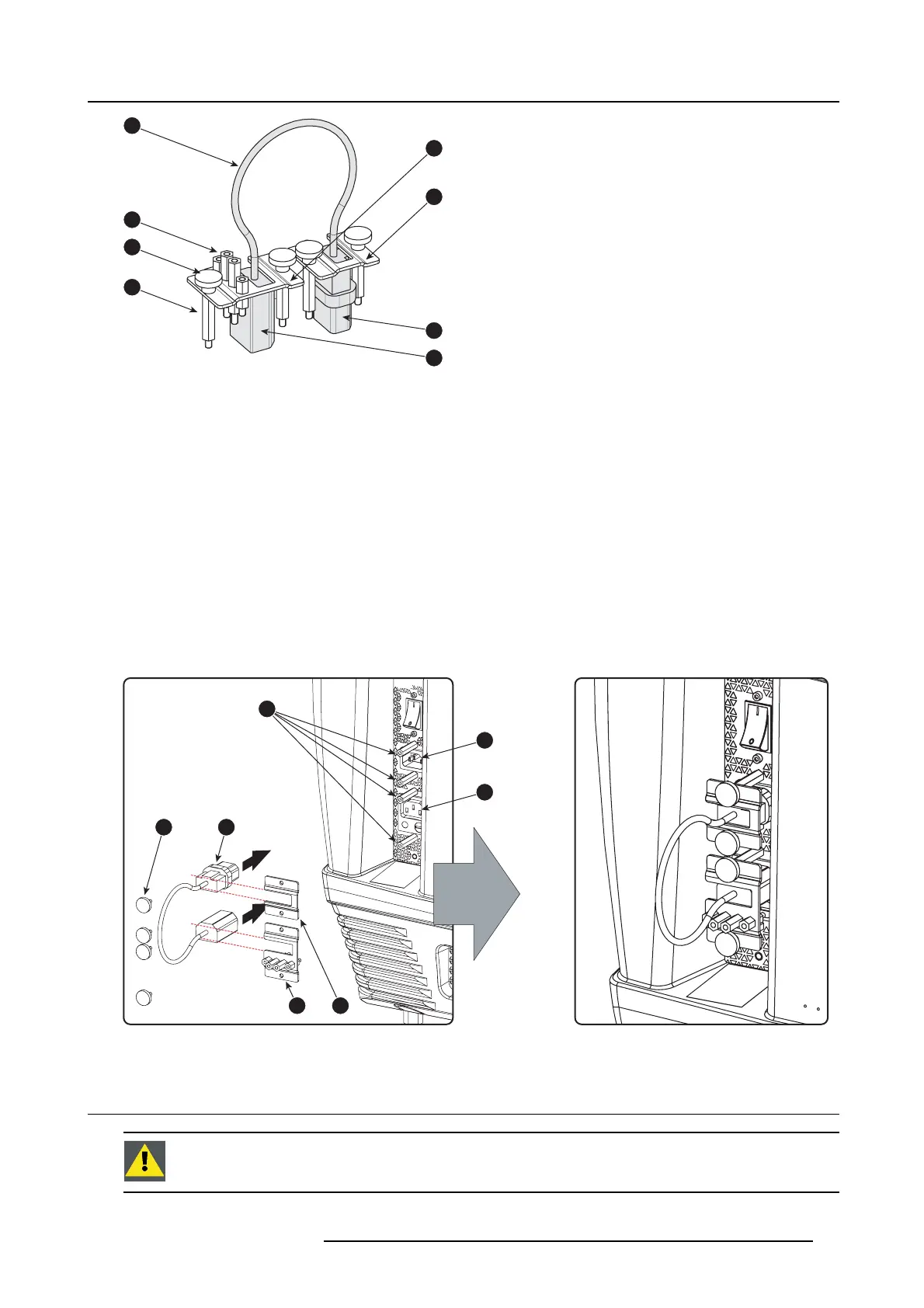
Image 3-10
1 Short power link cable (loop through).
2 Spare spacers with different length.
3 Thumbscrews.
4 Long spacers.
5 Fixation bracket for the female plug (OUTLET).
6 Fixation bracket fo r the m ale plug (INLET).
7 Male plug.
8 Female plug.
Necessary parts
Short power link c able with plug type C13/C14.
How to loop through the power to the projector electronics?
1. Make sure that a long spacer (reference 1) is m ounted above and below eac h power socket (reference 2 &3).
2. Plug in the short pow er cable (reference 4) which wa s delivered with the projec tor.
Warning: A lways use the Barco short power cable which is d elivered with the projector.
3. Secure both plugs of the short power cable with a fixation plate. Use two thumbscrews (reference 5) per fi xa tion plate. Note
that the smallest fixation plate (reference 7) h as to be used upon the upper s ocket (INLET, reference 2). The large fixation plate
(reference 6), w hich holds the spare spacers, has to be mounted upon the lower socket (OU TLET, reference 3).
1
2
3
5 4
76
Image 3-11
3.5 Connecting a U PS w ith the p rojector electronics
WARNING: O nly use UPS units w hic h are suitable for the D P2 K C- series p rojector. See chapter Installation
requirements, for more information about the requirements of the UPS.
R5905050 DP2K C-SERIES 10/07/2012 19
 Loading...


