6. Input & communication
6.3 Communication ports of the DP2K C-series projector
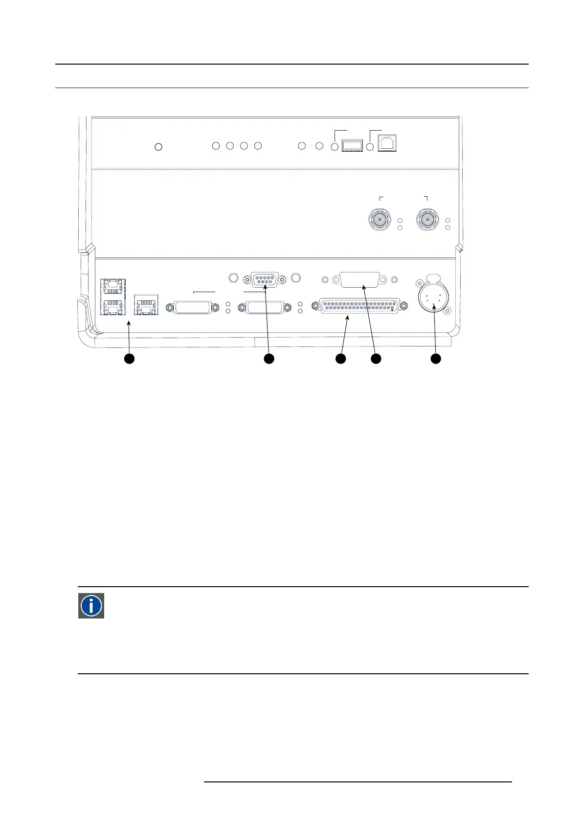
Location of the communication ports
GENERAL PURPOSE IN/OUT
DVI A DVI B
DVI INPUT
SEL
SYNC OK
SEL
SYNC OK
10 / 100 / 1000 BASE-T
RS232 IN 3D INTERFACE PERIPHERAL PORT
SMPTE 292/424 IN
AB
SEL
SYNC OK
SEL
SYNC OK
1
2
3
ICP
POWER
SW
STAT
OS
STAT
FMT
STAT
ICP
STAT
CINEMA
ALT
CONT
USB
OUT
USB
IN
1 2 3 4 5
Image 6-3
Communication ports
1 10/100/1000 base-T
2RS232IN
3 General purpose input/output (GPIO)
4 3D interface
5 Peripheral port
10/100/1000 BASE-T
The DP2K C-series projector can be connected to a LAN (local area network) using one of the E thernet ports (1). O nce connected
to the LA N, users can access the projector from any location, inside or outside (if allowed) their company network u sing the Com-
municator software. This software locates the projector on the network if there is a DHCP server or the user can insert the correct
IP-address to access the projector. O nce accessed, it is pos sible to c heck and manipulate all the projector settings. Remote diag-
nostics, control and monitoring of the projec tor c an then bec ome a daily and v ery simple operation. The network connectivity allows
detection of potential errors and cons equently im prove service time.
As there is a ne ed to daisy chain projectors when th ey are on an Ethernet network, an Ethernet switch is built in. the incoming
network is hereby available for the internal PC and for the next device in the chain. In this wa y a ’star ’ network interconnection can
be avoided. The switch use
d is a stand alone 10/100/1000Mbit Ethernet switch. This as sures no influence on the network speed.
RS232 IN
This female D B-9 connector allows you to use a standard s erial cable up to 10 meter to connect t he touch panel interface with the
projector. Note that the R S 232 protocol is used on this connection.
RS232
An Electronic Industries Association (EIA) serial digital interface standard specifying the characteristics of t he commu-
nication path between two devices using either D-SUB 9 pins or D-SUB 25 pins connectors. This s tandard is used for
relatively short-r
ange communications and do es no t specify balanced control lines. R S-232 is a se rial control s tandard
with a s et number of conductors, data rate, word length and type of connector to be used. The standard specifies com -
ponent connection standards with regard to c omputer interface. It is also called RS-232 -C, which is the third version
of the RS -232 sta
ndard, and is functionally identical to the CCITT V.24 standard. Logical ’0’ is > + 3V, Logical ’1’ is < -
3V. The range between -3V and +3V is the transition zone.
GENERAL PURPOSE IN/OUT
This 37 pin connector c an be us ed to send or receive trigger signals from other devices. These input/output pins can be programm ed
by macros created on the Com municator touch pane l. S ee user ’s guide of the Touc h panel, section Macro editor, for more informa-
tion about thi
s functionality. Note that the General Purpose Inputs accept 24 volt maximum.
3D INTERFACE
Optional port.
R5905050 DP2K C-SERIES 10/07/2012
49
 Loading...


