Mounting and wiring
BC3150 21Version: 2.1.0
3.2.3 PROFIBUS Connection
M12 round connector
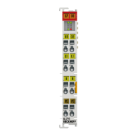
The M12 socket is inverse-coded and has five pins. Pin 1 transfers 5V
DC,
pin 3 transfers GND for the active
termination resistor. These must never be misused for other functions, as this can lead to destruction of the
device.
Pins 2 and 4 transfer the PROFIBUS signals. These must never be swapped over, as this will prevent
communication. Pin 5 transfers the shield, which is capacitively connected to the base of the Fieldbus Box.
Pin assignment M12 socket (-B310)
Fig.10: Pin assignment M12 socket (-B310)
Pin assignment M12 socket/plug connector (-B318)
Fig.11: Pin assignment M12 socket/plug connector (-B318)
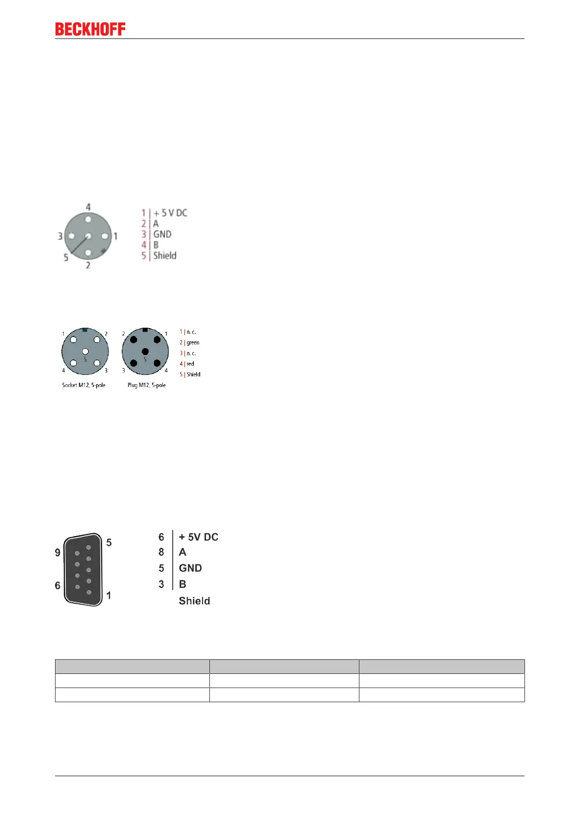
Nine-pin D-Sub
Pin 6 transfers 5V
DC,
pin 5 transfers GND for the active termination resistor. These must never be misused
for other functions, as this can lead to destruction of the device.
Pins 3 and 8 transfer the PROFIBUS signals. These must never be swapped over, as this will prevent
communication.
Pin assignment of the PROFIBUS D-sub socket
Fig.12: Pin assignment of the PROFIBUS D-sub socket
PROFIBUS wire colors
PROFIBUS line M12 D-Sub
B red Pin 4 Pin 3
A green Pin 2 Pin 8
Connection of the FieldbusBoxmodules
The FieldbusBoxmodules are connected either directly or via a T-piece (or Y-piece).

 Loading...