Error handling and diagnosis
BC3150 89Version: 2.1.0
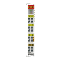
Fig.80: Display of the K-bus status in the variable K-bus state
Error bit Description Error type
0 No error No ERROR.
Bit 0 K-bus error ERROR
Bit 2 K-Bus is re-triggered NOTE
Reading K-bus state by ADS
In default or TwinCAT configuration the fieldbus status can be read via ADSREAD.
Parameter ADSREAD function block Description
NetID local – empty string
Port 1
IndexGroup 16#0006
IndexOffset 16#000C_9000
LEN 1
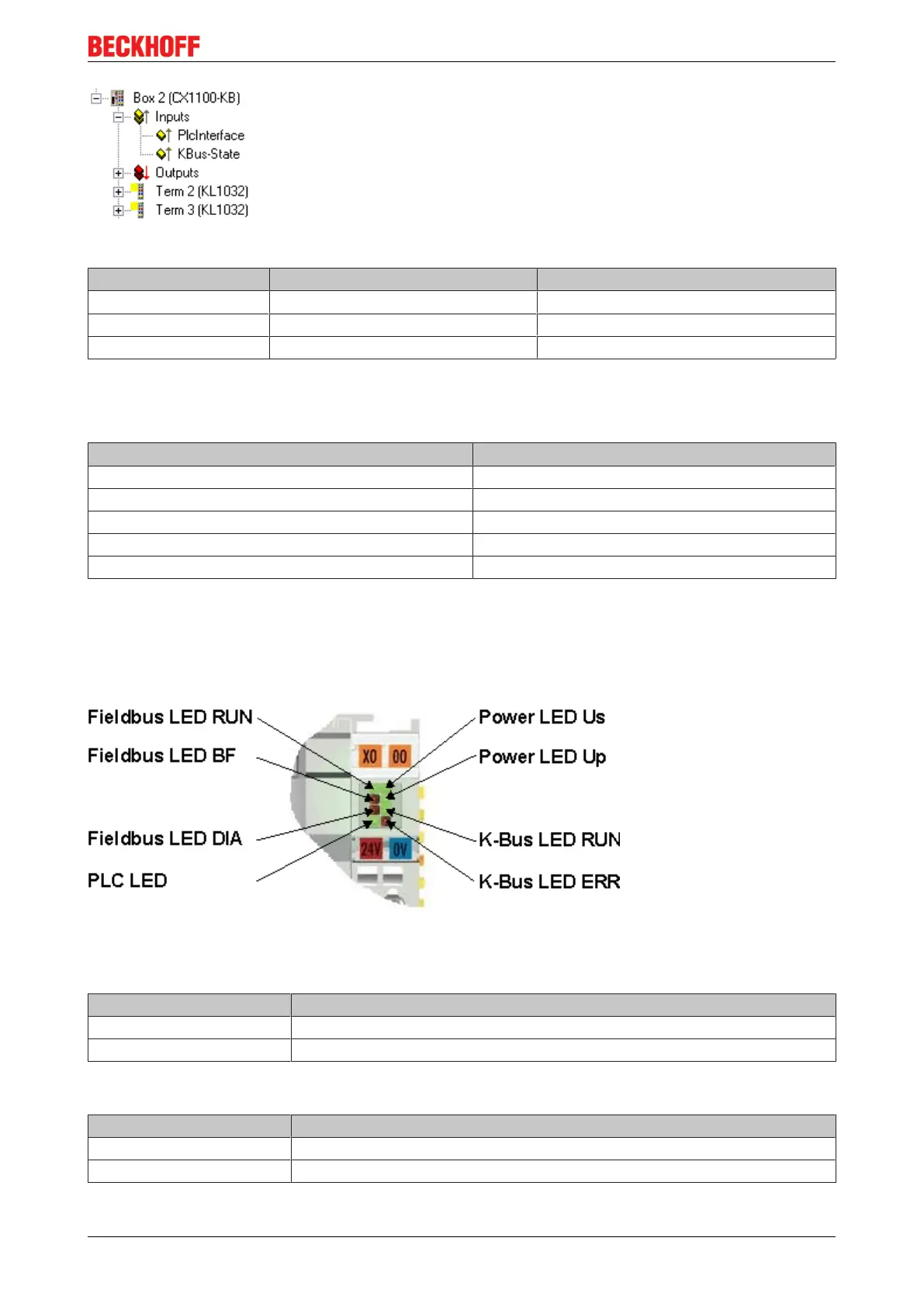
7.2 Diagnostic LEDs
The Bus Coupler features status indicator LEDs. The row of LEDs on the left describes the status of the
fieldbus and of the PLC. The row of LEDs on the right indicates the supply voltage and the K-Bus state.
Fig.81: LEDs
LEDs for power supply diagnostics
LED (Power LEDs) Meaning
LED Us LED off: Bus Coupler has no voltage 24 V
DC
LED Up LED off: No 24 V
DC
power supply connected to the power contacts
LEDs for K-Bus diagnostics
LED (Power LEDs) Meaning
LED RUN LED off: no K-Bus update, LED on, flashing: K-bus running
LED ERR LED off: no error, LED flashing: see K-Bus error code

 Loading...