EasyManua.ls Logo

Beckhoff BC3150 User Manual

Beckhoff BC3150
104 pages
To Next Page IconTo Next Page
To Previous Page IconTo Previous Page
Page #51 background image
Parameterization and Commissioning
BC3150 51Version: 2.1.0
Fig.48: Displaying the PLC cycle time
4.2.10 Setting the slave address
The address must be set via the two rotary selection switches. The default setting is 11. All addresses are
permitted, although each address may only occur once within the network. For changing an address the Bus
Coupler must be switched off. The switches can be set to the required position using a screwdriver. Ensure
that the switches engage correctly. The lower switch is the ten-multiplier, the upper switch is the one-
multiplier. The change in address is active as soon as the module is switched on.
Example
You want to set address 34:
Lower rotary selection switch Sx11:3
Upper rotary selection switch Sx10:4
Special functions using the address switch
In addition, the address switch can be used for following functions. To this end the associated address has to
be set (as long as the coupler is switched off), only the end terminal may be connected (KL9010), and the
coupler must then has to be connected to the supply voltage.
Address 99: Manufacturer's setting
Address 98: Delete boot project
Address 97: Delete TwinCAT configuration

Table of Contents

Question and Answer IconNeed help?

Do you have a question about the Beckhoff BC3150 and is the answer not in the manual?

Beckhoff BC3150 Specifications

General IconGeneral
BrandBeckhoff
ModelBC3150
CategoryController
LanguageEnglish

Summary

Foreword and Documentation

Notes on Documentation

Information regarding documentation usage, audience, disclaimers, trademarks, and patents.

Safety Instructions and Precautions

Essential safety regulations, liability exclusion, personnel qualification, and symbol explanations.

Documentation Issue Status

Details on document version history, changes made, and firmware information.

Product Overview and Technical Data

BCxx50 Overview and Bus Terminal Principle

Introduction to BCxx50 controllers, their features, and the basic structure of the Bus Terminal system.

Technical Specifications

Detailed technical data for BCxx50, PROFIBUS-DP, and PLC functionalities.

The Beckhoff Bus Terminal System

Overview of the system, including modularity, mounting, and bus coupler types.

Mounting and Wiring Guide

Mounting Procedures

Guidance on mounting the Bus Terminal system components, including dimensions and installation.

Wiring and Connection Details

Instructions for wiring, covering potential groups, power supply, PROFIBUS, and ATEX conditions.

Parameterization and Commissioning

Start-up Behavior

Describes the sequence of operations and checks performed by the controller upon startup.

Configuration and Setup Procedures

Covers TwinCAT config, ADS, PROFIBUS, K-bus, PLC setup, and slave addressing.

Configuration Software and Programming Cable

Details on using KS2000 software and the programming cable for setup.

Programming Guide

PLC Features and TwinCAT Setup

BCxx50 PLC features, TwinCAT PLC introduction, and initial setup.

PLC Error Handling and Data Management

Managing TwinCAT PLC errors, remanent data, and allocated flags.

Process Image, Terminal Mapping, and Boot Projects

Configuring process image, mapping terminals, and creating boot projects.

Program Transfer, Communication, and PROFIBUS

Methods for program transfer, communication, libraries, and PROFIBUS setup.

PROFIBUS System Introduction

Fieldbus Overview and PROFIBUS DP

Overview of PROFIBUS as an open standard and details on PROFIBUS DP for data exchange.

PROFIBUS DPV1 and Connections

Explanation of PROFIBUS DPV1 for acyclic telegrams and details on connectors and cables.

PROFIBUS Topology and Addressing

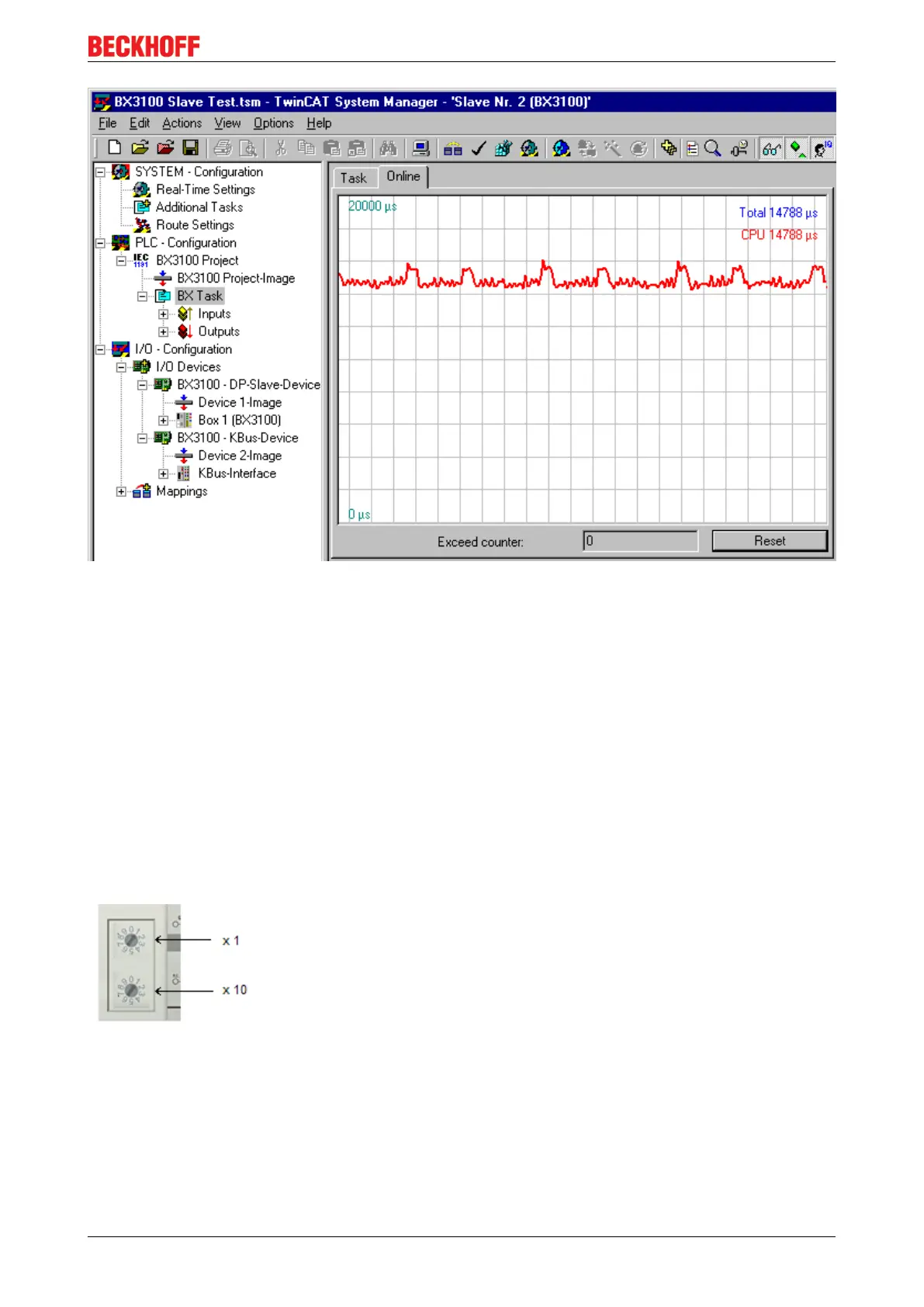
Guidelines for PROFIBUS topology and procedures for setting slave addresses.

Error Handling and Diagnostics

Diagnostics and Status Monitoring

Methods for diagnosing PROFIBUS state, reading fieldbus status via ADS, and K-bus status.

Diagnostic LEDs and K-Bus Error Codes

Explanation of diagnostic LEDs and a table of K-Bus error codes with remedies.

Appendix and Support

Getting Started and Controller Migration

Initial setup guide for BC3150 and instructions for switching between controllers.

Firmware Update and Operating Conditions

Procedures for firmware updates and general operating conditions for fieldbus components.

Device Testing Standards and References

Test standards for devices and bibliography of relevant technical resources.

Abbreviations and Support

List of abbreviations and information on Beckhoff support and service contacts.

Related product manuals