Programming
BC9000 and BC910040 Version: 4.0.0
Sample
400bytes of remanent data, of which 200bytes should be persistent
Register 15 400(%MB200 ... %MB399)
Register 18 200(%MB0 … %MB199)
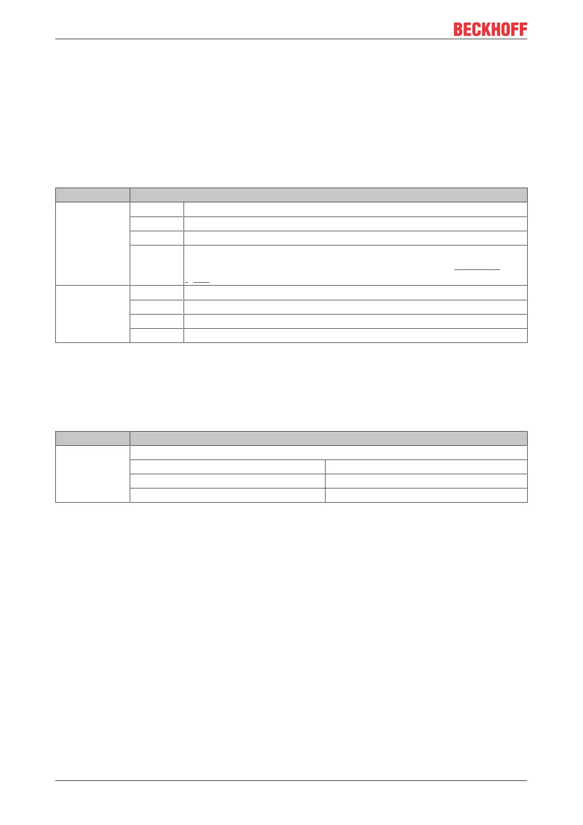
6.6.2 Diagnostics
It is possible to read the diagnostic data in the Bus Terminal Controller. This information is located in the
flags area.
Flag byte Meaning
%MB4092-4093 Bit 0 ADS communication watchdog
Bit 1 ModbusTCP communication watchdog
Bit 1…14 reserved
Bit 15 No connection to switch: The Link LED does not light up (the transfer of this
error information is disabled in delivery state. To enable it, set register 25
[}77] in table100 to 1
bin
).
%MB4094-4095 Bit 0 K-bus error
Bit 1 Configuration error
Bit 2 K-bus cycle time exceeded (see table 1, register 17)
Bit 3…15 reserved
6.6.3 Cycle Time Measuring
The flags area includes a time measurement with a resolution of one millisecond for each digit. The data
type is UDINT (unsigned double integer). This value can be overwritten by the program, in order to align with
a controller. The overflow occurs after approx. 48days.
Flag byte Meaning
%MB4088-4091 4bytes
Data type UDINT
0...4.22billionms / 0... approx. 48 days
Resolution 1ms / digit
6.7 Fieldbus process image
6.7.1 Fieldbus process image
16bytes input and output are assigned to the fieldbus by default in all the BCxxxx devices. These variables
are known as the PLC variables. They are located by default in the BCxxxx process image starting at
address 128. This address can be shifted. The setting can be made with the KS2000 configuration software,
or, for some BCs, can be changed by means of start-up parameters.
6.7.2 ModbusTCP Process Image
The ModbusTCP process image makes a fundamental distinction between digital and byte-oriented (word-
oriented) signals. This will be clarified by examples.
 Loading...


