Error handling and diagnosis
BC9000 and BC910078 Version: 4.0.0
8 Error handling and diagnosis
8.1 Diagnostic LEDs
BK9000, BK9100, BC9000, BC9100
After switching on, the Bus Coupler immediately checks the connected configuration. Error-free start-up is
indicated when the red I/O ERR LED goes out. If the I/O ERR LED blinks, an error in the area of the
terminals is indicated. The error code can be determined from the frequency and number of blinks. This
permits rapid rectification of the error.
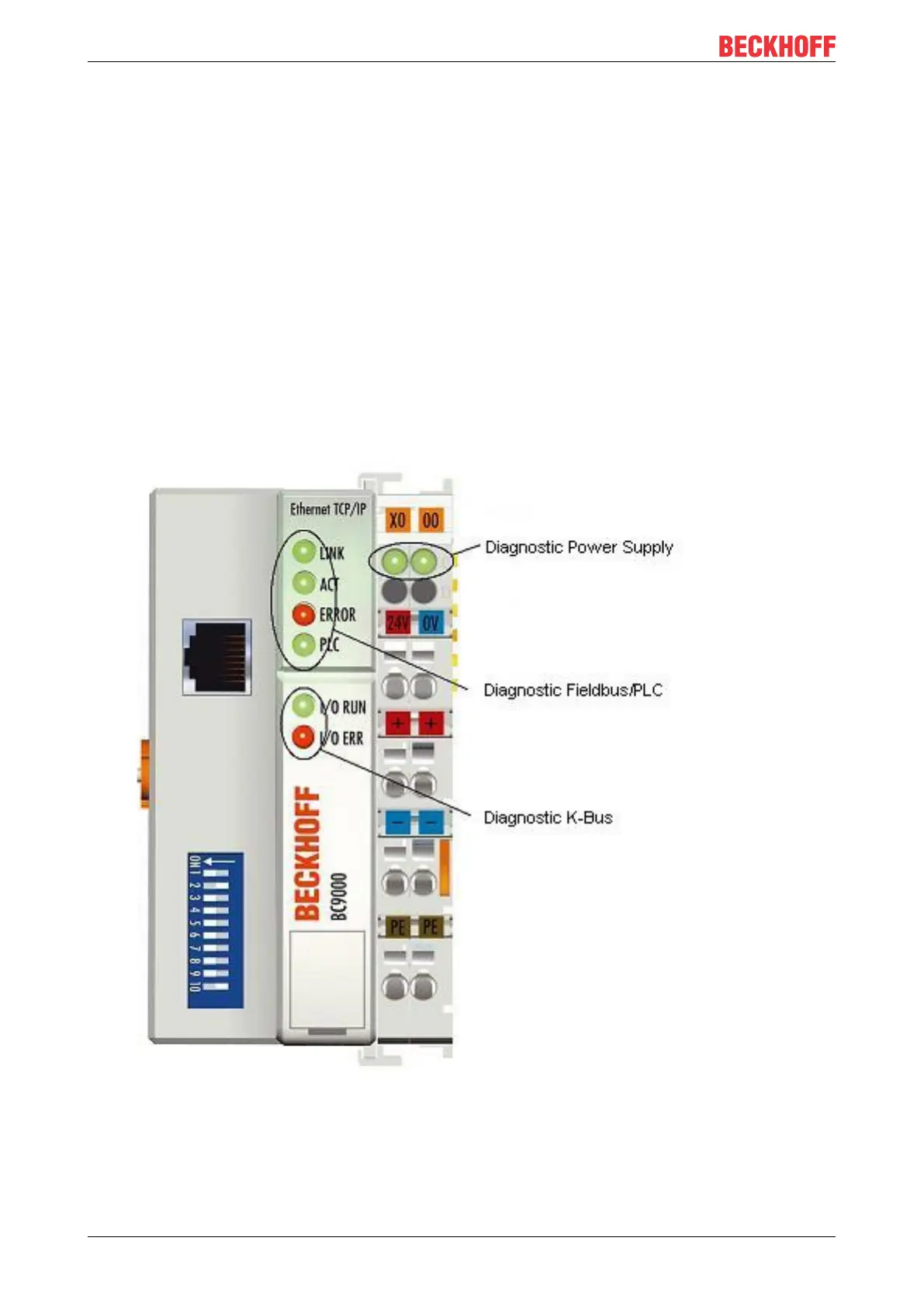
The Bus Coupler has two groups of LEDs for the display of status. The upper group with four LEDs indicates
the status of the respective fieldbus. The significance of the fieldbus status LEDs is explained in the
appropriate sections of this manual. It corresponds to the usual fieldbus display.
On the upper right hand side of the Bus Couplers are two more green LEDs that indicate the supply voltage.
The left hand LED indicates the presence of the 24V supply for the Bus Coupler. The right hand LED
indicates the presence of the supply to the power contacts.
Fig.49: BC9000 - LEDs
 Loading...


