List of illustrations
BC9000 and BC9100 89Version: 4.0.0
List of illustrations
Fig. 1 Principle of the Bus Terminal....................................................................................................... 8
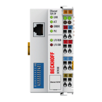
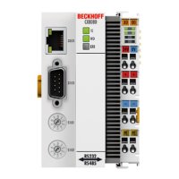
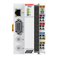
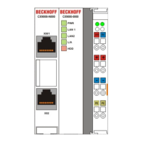
Fig. 2 BC9000 and BC9100................................................................................................................... 10
Fig. 3 Dimensions .................................................................................................................................. 13
Fig. 4 Electrical isolation ........................................................................................................................ 16
Fig. 5 Ethernet layout in star topology ................................................................................................... 17
Fig. 6 Ethernet layout in linear topology ................................................................................................ 18
Fig. 7 RJ45 connector (Western plug) ................................................................................................... 19
Fig. 8 Ethernet connection via hub or switch ......................................................................................... 19
Fig. 9 Direct Ethernet connection (crossover cable).............................................................................. 19
Fig. 10 Start-up behavior of the Bus Terminal Controller ........................................................................ 22
Fig. 11 Network classes........................................................................................................................... 24
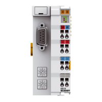
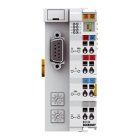
Fig. 12 BK9000, BK9100, BC9000, BC9100 ........................................................................................... 25
Fig. 13 BK9050 ........................................................................................................................................ 25
Fig. 14 Configuration of the Beckhoff BootP server................................................................................. 27
Fig. 15 Adressing by name ...................................................................................................................... 28
Fig. 16 Testing the IP address using the Ping command ........................................................................ 29
Fig. 17 Security settings .......................................................................................................................... 30
Fig. 18 Reading the connected Bus Couplers and Bus Terminals .......................................................... 31
Fig. 19 Setting the router memory ........................................................................................................... 31
Fig. 20 The IP Address tab ...................................................................................................................... 32
Fig. 21 PLC tab........................................................................................................................................ 33
Fig. 22 Sample configuration of a Bus Terminal Controller ..................................................................... 35
Fig. 23 Program running time .................................................................................................................. 36
Fig. 24 Task Time .................................................................................................................................... 37
Fig. 25 Bus Terminals in the BC's local process image........................................................................... 37
Fig. 26 Assign bus terminals to the higher level controller ...................................................................... 38
Fig. 27 Selection of the target platform.................................................................................................... 42
Fig. 28 Communication parameters......................................................................................................... 42
Fig. 29 The menu behind the TwinCAT icon ........................................................................................... 43
Fig. 30 TwinCAT system properties......................................................................................................... 43
Fig. 31 Add remote connection................................................................................................................ 44
Fig. 32 TwinCAT System Manager.......................................................................................................... 44
Fig. 33 Selection of the target platform.................................................................................................... 45
Fig. 34 Choose Target System ................................................................................................................ 45
Fig. 35 Function block RW_FIELDBUSPRMBC9000 .............................................................................. 47
Fig. 36 Function block RW_PARAMETERBC9000 ................................................................................. 48
Fig. 37 Function block FB_SNTP ............................................................................................................ 49
Fig. 38 User Datagram Protocol (UDP) ................................................................................................... 52
Fig. 39 Protocols running on top of TCP/IP and UDP/IP ......................................................................... 52
Fig. 40 The ADS protocol as a transport layer within the TwinCAT system ............................................ 54
Fig. 41 Structure of the ADS protocol ...................................................................................................... 55
Fig. 42 Displaying the AMS routing table using the KS2000 configuration software ............................... 60
Fig. 43 ADS connection ........................................................................................................................... 61
Fig. 44 Bus structure for cross communication........................................................................................ 62

 Loading...
