Product overview, digital output terminals
EL20xx, EL212446 Version: 5.2
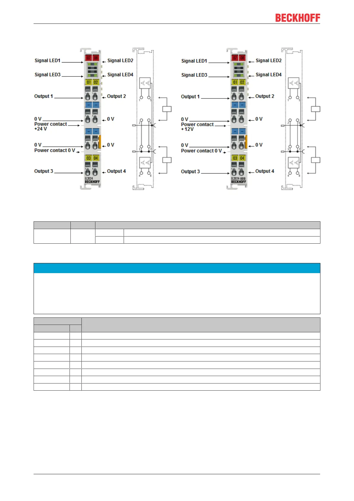
2.3.3 EL2024, EL2024-0010 - LEDs and connection
Fig.31: EL2024, EL2024-0010
EL2024, EL2024-0010 - LEDs
LED Color Meaning
OUTPUT 1- 4 green off No output signal is present.
on A 24V
DC
output signal (EL2024) or 12V
DC
output signal (EL2024-0010) is present
EL2024, EL2024-0010 - Connection
NOTE
12 V DC at the power contacts of the EL2024-0010
During configuration of the Bus Terminal block, please note that the power contacts of the EL2024-0010
carry a voltage of 12V
DC
(provided e.g. by an EL9512 power supply terminal).
If 24V terminals are to operate in the terminal block simultaneously, measures must be implemented for
electrical isolation (e.g. through the EL9190 power feed terminal or the EL9080 separation terminal).
Terminal point Description
Name No.
Output 1 1 Output 1
0V 2 Ground for output1 (internally connected to terminal point3, 6, 7 and negative power contact)
0V 3 Ground for output3 (internally connected to terminal point2, 6, 7 and negative power contact)
Output 3 4 Output 3
Output 2 5 Output 2
0V 6 Ground for output2 (internally connected to terminal point2, 3, 7 and negative power contact)
0V 7 Ground for output4 (internally connected to terminal point2, 3, 6 and negative power contact)
Output 4 8 Output 4

 Loading...