Technical description
6.1.3 Connection overview
Slot assignment of the power voltage
For produce a power supply, connect the Harting plug of the starter kit with the Harting slots on the control
cabinet.
Line identification Slot Signal Wire cross section
Phase 1 Pin 1 +48 V 2.5 mm²
Phase 2 Pin 2 GND (48 V) 2.5 mm²
Phase 3 Pin 3 +24 V 0.75 mm²
Phase 4 Pin 4 GND (24 V) 0.75 mm²
green and yellow phase screwed to the side Functional earth 2.5 mm²
Note
Design of the wire cross-sections
The cable length (supply voltage + EtherCAT) of the supply modules is 5 m. The cable end
of the supply voltage is pre-assembled with ferrules. The EtherCAT cable end is pre-as-
sembled with an RJ45 connector.
Slot assignment of the EtherCAT lines
For produce an EtherCAT connection, connect the EtherCAT cables with the corresponding labeled slots on
the control cabinet. If the cables are reversed, agree the teaching data of the respective modules will no
longer match.
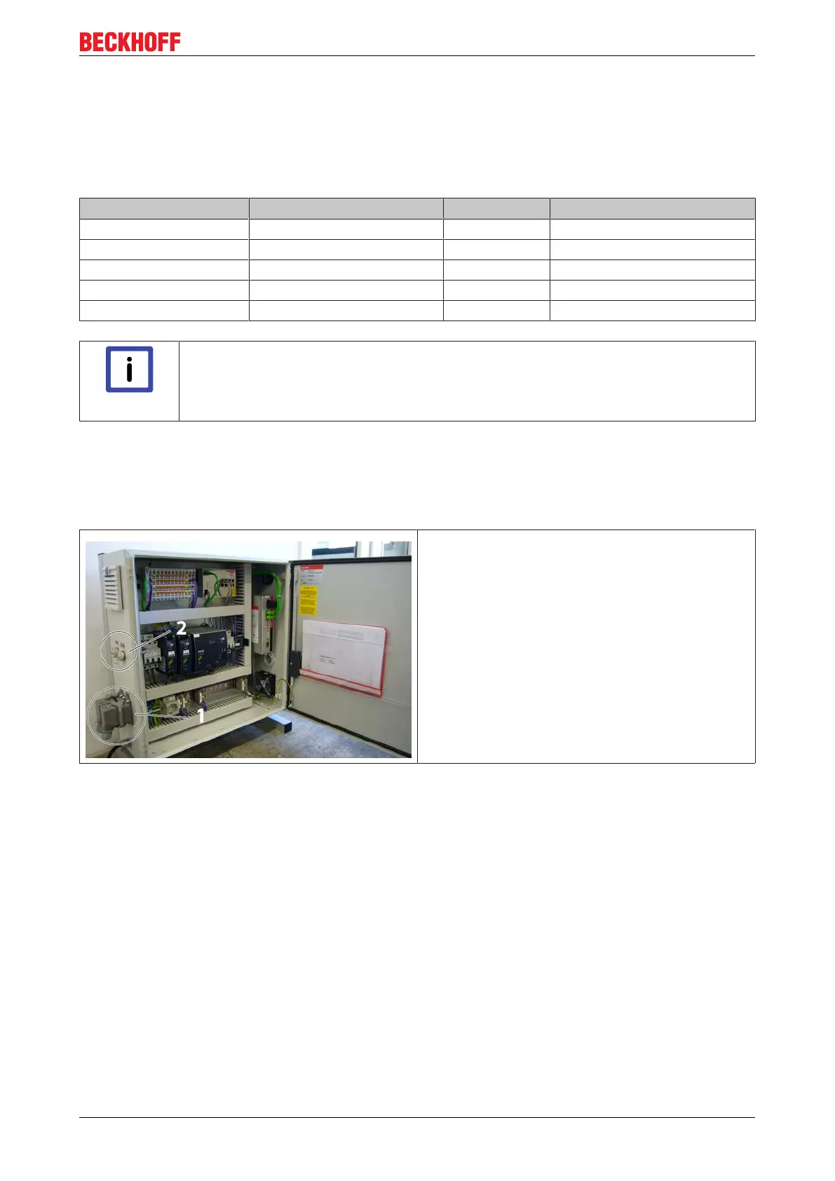
• Pos. 1 shows the two places of assignment for
the Harting connector of the XTS.
• Pos. 2 shows the input and output slot for the
EtherCAT connection
eXtended Transport System Start-Up 21
Version: 1.2

 Loading...