Technical description
6.4 Overview of the components
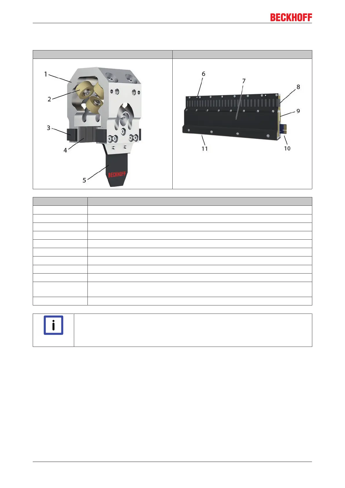
Mover 6 rollers Straight motor module
Position number Description
1 Mover body
2 Rollers
3 Rubber bumper
4 Magnet plates
5 Encoder flag for position measurement
6 Track mounting surface
7 Encoder flag detection surface
8 Motor coils
9 Dowel pin hole for alignment
10 Module to module connection card. Transmits control power (24 V) DC bus (50 V)
power and EtherCAT between modules.
11 Machine bed mounting surface
Note
Alignment Dowel Pins
Exact locations and dimensions of the dowel pins are given in the 3D drawings (.stp files) of
the motor modules. For further information please contact the Beckhoff applications depart-
ment.
eXtended Transport System Start-Up26
Version: 1.2

 Loading...