About this product 19/60
RE 92801-01-B/11.2018, A15VSO/A15VLO Series 11, BoschRexrothAG
5.2.2 Functional description
Torque and rotational speed are applied tothe drive shaft(1) byadrive motor. The
drive shaft isconnected tothe cylinder (9) bysplines, causing the cylinder torotate.
With every revolution, the pistons(10) perform astroke inthe cylinder bores, the
size ofwhich depends onthe pitch ofthecradle(12). The slipper pads(11) are held
onwith the pistons and guided along the glide surface ofthecradle bytheretaining
plate(2). The pitch oftheswashplate during arevolution causes each piston tomove
over the bottom and top dead centers and back toits initial position. Hydraulic fluid
isfed into and out through two control slots inthe control plate(7) according
todisplacement. Hydraulic fluid flows into the piston chamber asthepiston recedes
onthe suction side (8). At the same time, the hydraulic fluid ispushed out
ofthecylinder chamber into the hydraulic system bythepistons onthe high-
pressure side (3).
The swivel angle ofthecradle(12) isinfinitely variable. Controlling the swashplate
swivel angle changes the piston stroke and, therefore, the displacement. The swivel
angle iscontrolled hydraulically bymeans ofthestroking piston. The cradle
ismounted inswivel bearings for smooth operation, and itiskept inbalance
bytheopposed piston (not illustrated). Increasing the swivel angle increases the
displacement; reducing the angle reduces displacement accordingly.
Various control devices are available depending onrequirements. Information
about this can befound indata sheet 92801.
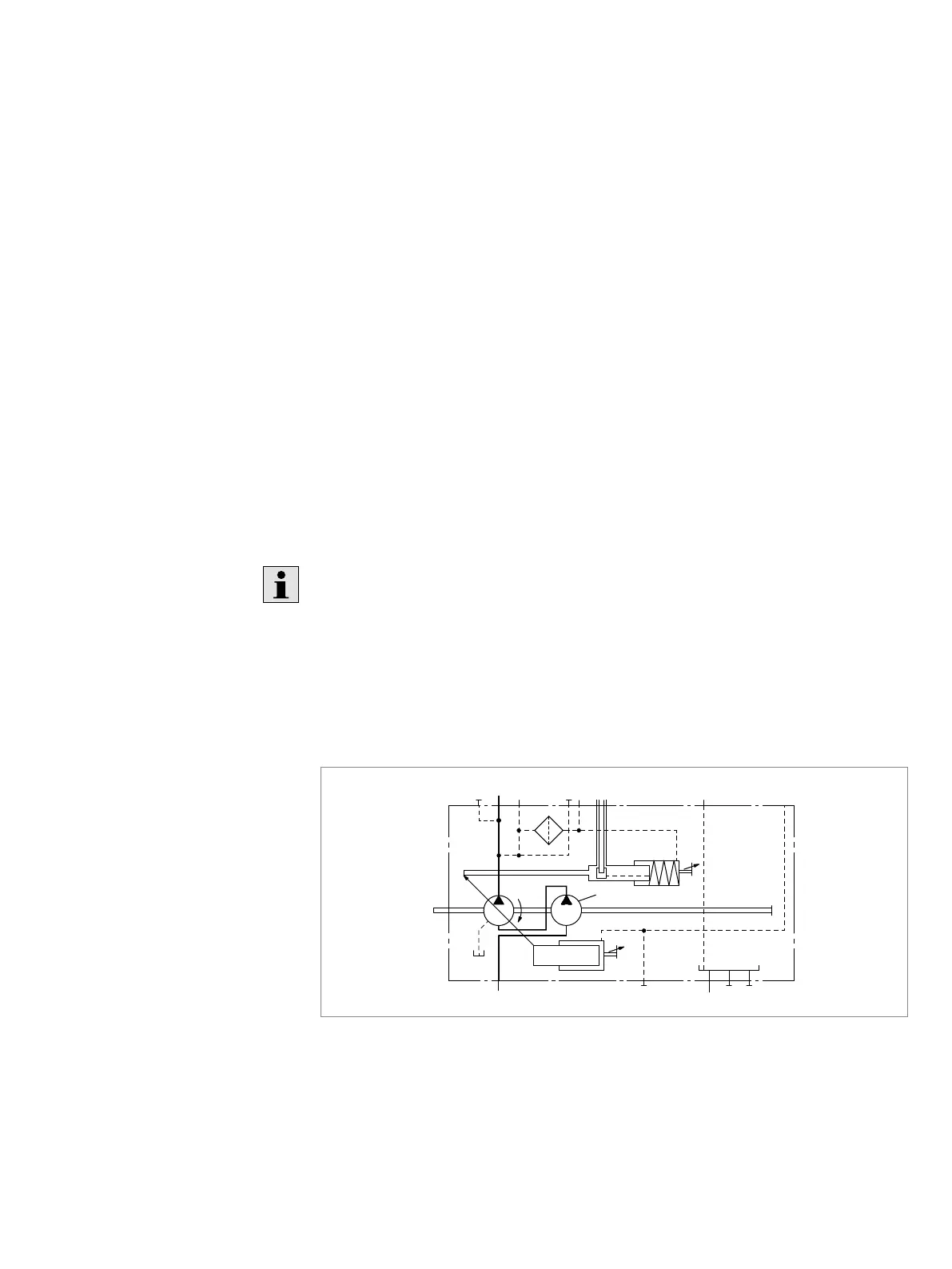
The axial piston unit A15VLO isequipped with acharge pump(4). The charge pump
(impeller) isacentrifugal pump with which the pump isfilled and can beoperated
athigher rotational speeds. This also simplifies cold starting atlow temperatures
and high viscosity ofthehydraulic fluid. Externally increasing the inlet pressure
istherefore unnecessary inmost cases. Charging the reservoir with compressed air
isnot permissible.
M
A
A P
V
g min
V
g max
S M T
2
T
3
T
1
4
Fig. 3: Circuit diagram A15VLO with charge pump
Pump function
Control
Charge pump (optional)
 Loading...


