Callout --Description Callout --Description
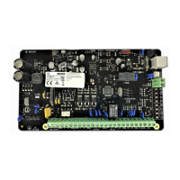
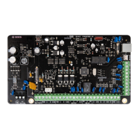
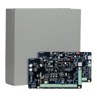
1 – Socket for telecom lead connect 8 – Bosch SDI2 Bus
2 – Receiver interface connection 9 – Battery input
3 – Tamper switch 10 – Plug pack input (Bosch TF008)
4 – Zone 5-8 termination strip
( Zone 5 – 8 and Zone 13 – 16 for Solution
3000 )
11 - Bosch SDI2 Bus
5 – AUX power 12 – Relay contact select (Select output AUX
as shown or output GND)
6 – Zone 1-4 termination strip
( Zone 1 - 4 and Zone 5 – 8 for Solution
2000 ;
Zone 1 – 4 and Zone 9 – 12 for Solution
3000 )
13 – LED indicator
7 – Output termination strip 14 – Default button
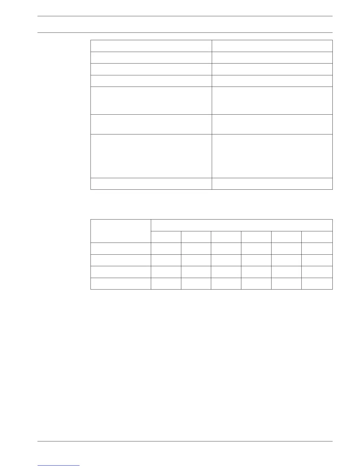
Table 5.5: Callout description
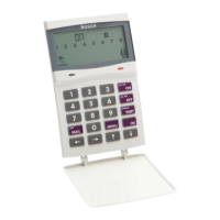
Codepad Address Setting
DIP Switch Codepad
Address
DIP Switch Number
1 2 3 4 5 6
1 On Off Off Off Off On
2 Off On Off Off Off On
3 On On Off Off Off On
4 Off Off On Off Off On
Table 5.6: Codepad DIP switch address setting
DIP switch address settings are only for IUI-SOL-TEXT or IUI-SOL-ICON codepad.
5.4
Control Panel Appendices | en 51
Bosch Security Systems, Inc. Quick Reference Guide 2015.06 | 03 | F.01U.298.027
 Loading...