9
8
7
6
5
4
2
1
11
3
12
10
13
RBM84 -
Hardware and connections
7
Page
-
Manual code:
FA00189M04 ver.
10/2015
© CAME s.p.a. - The data and information provided in this manual are subject to change at any time without prior notice by CAME S.p.a.
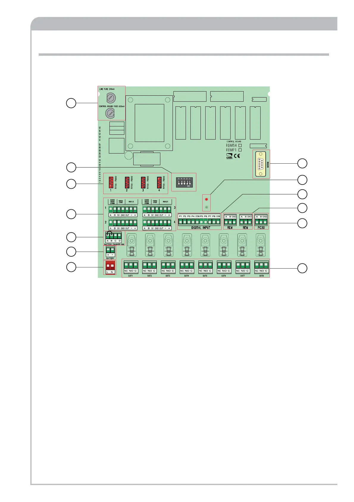
RBM84 base board - description
1. 315mA safety fuses (Line) and 630mA circuit fuses
(control board)
2. R700 and R800 board connector
3. Sensor connection terminal
4. LBD2BN1 battery charger board connection terminals
5. Battery connection terminals
6. 230V A.C. line connection
7. Connector terminal block for controlled devices, max. 5A
at 230V per contact.
8. Connection terminals for REM extensions/Wave connection
or PST001.
9. Connection terminals for input digital devices.
10. PC30 connection terminals
11. Signalling LEDs: red - "circuit active" - green -
"communication in progress".
12. Modem RS232 connector
13. Function selector (see p. 27)
 Loading...