11
6
4
5
10
9
4
7
8
1
2
3
RBM84 -
Hardware and connections
8
Page
- Manual code:
FA00189M04 ver.
10/2015 © CAME s.p.a. - The data and information provided in this manual are subject to change at any time without prior notice by CAME S.p.a.
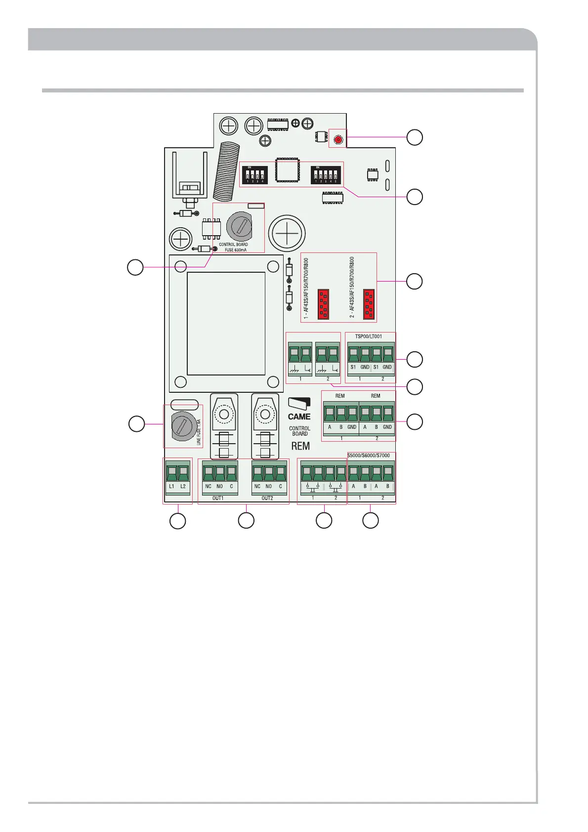
1. Power supply terminals for 230V A.C. board
2. Power supply safety fuse
3. Circuit safety fuse
4. Connection terminals for transponder sensors (TSP00) and
reader for magnetic stripe cards (LT001).
5. Connectors for signal decoding cards (selectors, sensors,
transmitters)
6. Antenna connection terminals
7. Connection terminals for digital input devices
8. Connection terminals for slave devices
9. "Circuit active" alert LED
10. Rem address selector (see p. 26)
11. Connection terminal block for segment subsequent device
(REM/WAVE/Turnstile).
RBM84 base board - description
 Loading...