DC10 E, DC20 E
SERVICE MODE / ADJUSTMENT
42
5-8-6 Contrast Adjustment
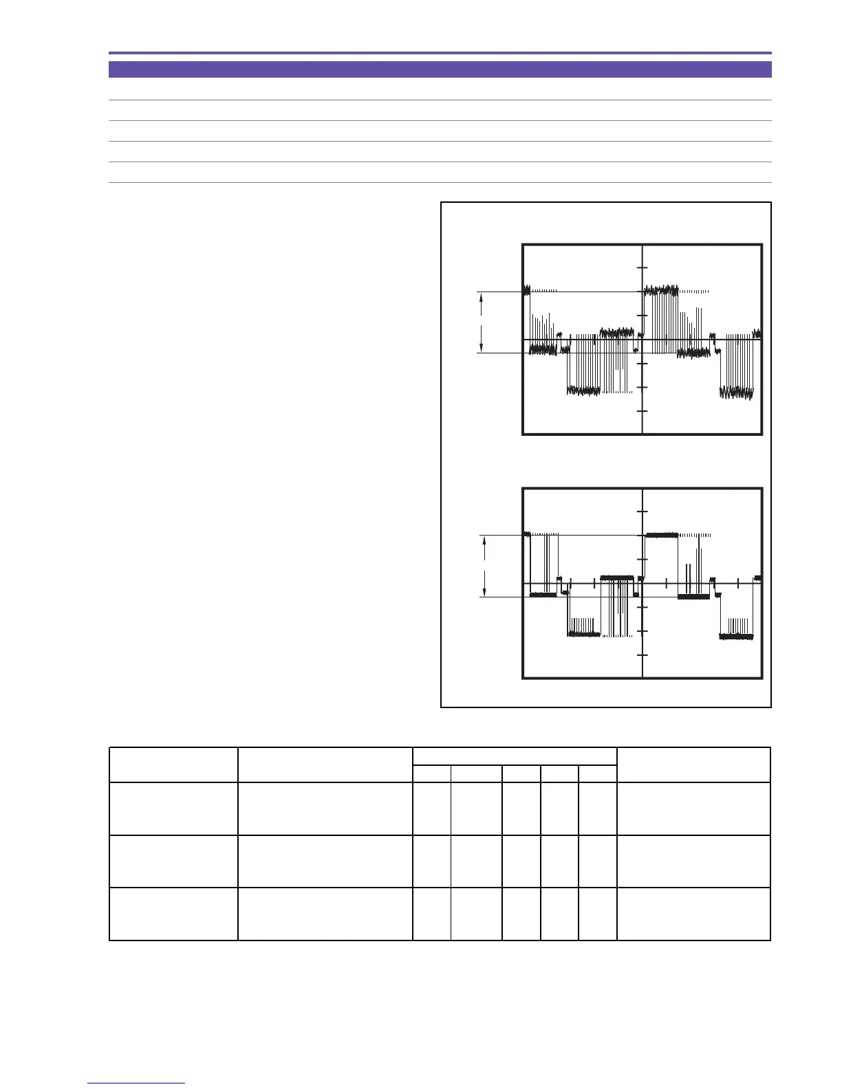
MODE Display of monochrome master
M. EQ. Oscilloscope
TP/TRIG. Extension connector - pin 15 (G), pin 13 (R), pin 16 (B), / TP signal (self TRIG)
SPEC. 2.30 ± 0.05 [V]
Procedure)
(1) Carry out adjustment according to the table shown below.
Note) In the service mode, the waveform observation
point is hard to locate. For locating the wave-
form observation point, transfer to the normal
mode beforehand.
Note) The adjustment sequence indicated above should be observed.
If the ST mode has been selected at the time of contrast adjustment, the black limiter is released automatically.
Therefore, it is not required to make setting in this case.
Be sure to perform adjustment (G) first, and then adjustments (R) and (B).
CS Function MD ADDR DT
Contrast Adjustment (G) 1) Make the setting shown at right. 0 21 ST 0007
"ADJ"
Start of setting
2) Perform storing.
↑↑
RD
↑
ADJ Completion of setting
(press the PAUSE button.)
Contrast Adjustment (R) 1) Make the setting shown at right. 0 21 ST 0009
"ADJ"
Start of setting
2) Perform storing.
↑↑
RD
↑
ADJ Completion of setting
(press the PAUSE button.)
Contrast Adjustment (B) 1) Make the setting shown at right. 0 21 ST 000B
"ADJ"
Start of setting
2) Perform storing.
↑↑
RD
↑
ADJ Completion of setting
(press the PAUSE button.)
STEP PROCEDURE
MONITOR
Microcomputer operation
Fig. 29
Service Mode
Normal Mode
2.30V
±
0.05V
2.30V
±
0.05V
 Loading...