8200-M129-O1 Rev D 205 Installation & Technical 8
WARNING! Disconnect any external load cell power supply before
connecting load cells to the indicator. Failure to do so will result in
permanent damage to the indicator.
INSTALLATION, CONT.
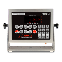
Load Cell Cable Connection for RFI Suppression
The load cell cable should be routed through the special metallic gland connector and the
shield wire must be connected to this gland connector for grounding and to eliminate RFI.
Refer to Figure No. 2 and Figure No. 3 for the appropriate gland connector.
1. Remove the 12 acorn nuts securing the back
panel to main housing.
2. Loosen and remove the metal gland
connector nut and remove the plastic insert.
3. Route the load cell cable through the nut and
plastic insert and into the enclosure.
4. With the load cell cable routed into the
enclosure, remove approximately 18 to 20
inches of the outer insulating jacket from the
cable exposing the internal wires.
5. Cut the shield wire so that it extends past the
outer jacket approximately 3/4 inch.
6. Remove 1/4" of insulation from the end of
each of the 4 wires (without sense leads) or 6
wires with sense leads (refer to figure No. 4).
7. Connect each of the wires to terminal block
P15 referring to labels on circuit board for
terminal connections. Refer to Figure No. 10
for terminal block location.
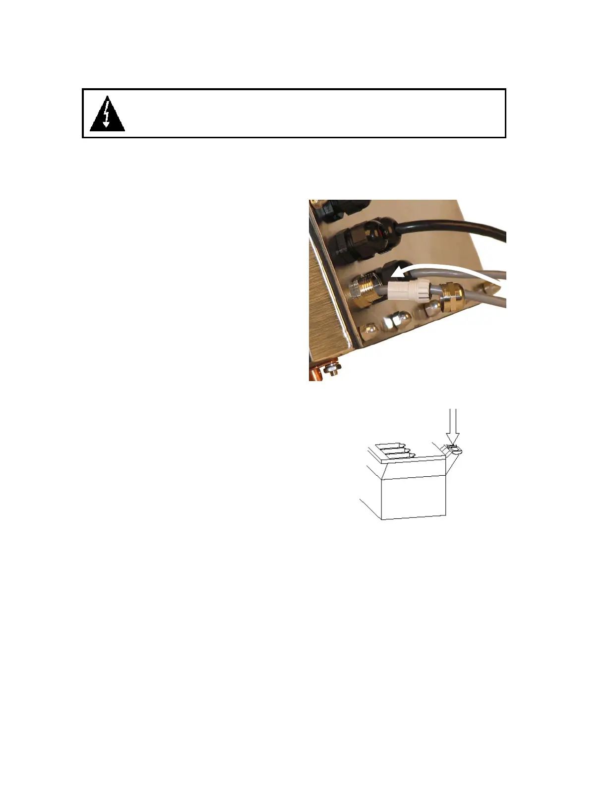
8. To terminate a wire, press down on release
bar for the terminal, insert wire into terminal
opening then allow release bar to return to its
original position, locking wire in place.
Repeat procedure until all wires are in place.
9. Route load cell cable wires through the two
cable clips provided on upper and left sides
of enclosure interior.
LOAD CELL TERMINAL BLOCK P15
TERMINAL NO. Function TERMINAL NO. Function
1 – +EXC + EXCITATION 5 – -SIG - SIGNAL
2 – +SEN + SENSE
6 – -SEN - SENSE
3 – +SIG + SIGNAL 7 – -EXC - EXCITATION
4 – SHLD SHIELD (Not used, load cell cable shield wire is connected to the
special metallic gland connector).
NOTE: If the sense leads are NOT used, you must install plug-in jumpers at J6 and J9
adjacent to the terminal block. These jumpers attach the sense leads to the excitation leads.
If sense leads ARE used (as in motor truck scales), these plug-in jumpers should be positioned
on one plug-in pin only or removed and stored for later use (see Figure No. 10).
Figure No. 3
Figure No. 4

 Loading...