8200-M129-O1 Rev D 205 Installation & Technical 23
SETUP AND CALIBRATION
Your Model 205 indicator has been
thoroughly tested and calibrated before
being shipped to you. If you received the
indicator attached to a scale, calibration
is not necessary. If the indicator is being
connected to a scale for the first time or
recalibration is necessary for other
reasons, proceed as indicated.
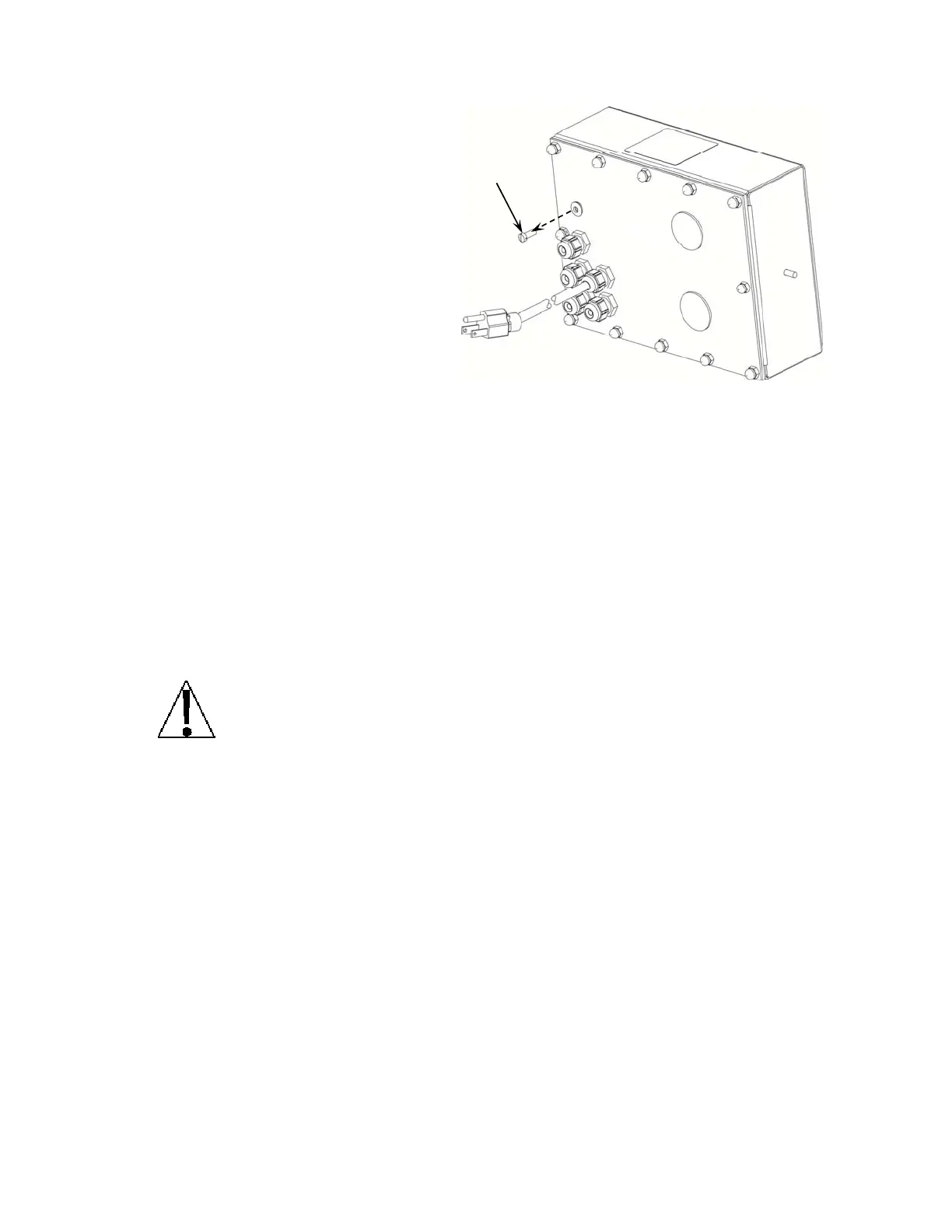
The calibration switch is located on a
bracket on the inside of the enclosure
rear panel. You may gain access to this
switch simply by removing the calibration
switch access screw on the rear panel.
Refer to Figure No. 12.
During the setup and calibration process it will be necessary to enter operational parameters
via the 205 keypad.
• Pressing the TARE/ENTER key will cause the data entered or displayed to be
retained and the 205 to advance to the next prompt.
• The functions of numeric keys are replaced by using the UNITS/LEFT ARROW and
the /UP ARROW keys.
• The cursor location is identified by the blinking character and can be advanced to the
left to the next position by pressing the UNITS/LEFT ARROW key.
• Pressing the /UP ARROW key will change the blinking character to the next value.
Continue to press this key to "toggle" between the different available values for the
setup parameter.
• Pressing the /UP ARROW key when a setup parameter (not a parameter value) is
displayed, will "backup" to the previous prompt.
DO NOT operate the keypad with pointed objects (pencils, pens, etc).
Damage to keypad resulting from this practice is NOT covered under warranty.
Enter Setup Mode
To enter the setup mode, with the indicator ON, insert a small screwdriver or other tool through
the calibration switch access hole on the rear panel. Press and release the calibration switch.
The menu SetUP will be displayed. Continue to press and release the switch to rotate
through the beginning point for entering the setup mode.
Setup Menus
SEtUP Setup Mode (starts at USA prompt)
A-d Analog to Digital Filtering (starts at dFLt= prompt)
CAL Calibration (starts at CAL1 prompt)
SSt Setup Guardian Scale (starts at tLoU prompt)
Sio Serial Input/Output (starts at Sio O? prompt)
Print Print Tab Settings (starts at POrt prompt)
F SPAn Fine Span Adjustment
Hi rES Display high-resolution weight mode
LoCoUt Key lock out function
option Option Card Configuration (only displayed when option card is installed)
Figure No. 12
Access
Screw

 Loading...