8200-M129-O1 Rev D 205 Installation & Technical 65
MODEL 205DC
The Model 205DC has been created to change the input power requirement from 115-230VAC,
0.4A to 12-15VDC, 1.0A. The AC input filtering and AC–DC converter components have been
removed from the back panel of the indicator.
The input power wiring and the main printed circuit board power wiring have been changed.
The input power source can be provided by the user and is to be 12-15VDC, 1A. The main
printed circuit board positive (red) power wire is connected to the L1(H) terminal and the
negative (black) wire is connected to the GND terminal of the input power terminal block.
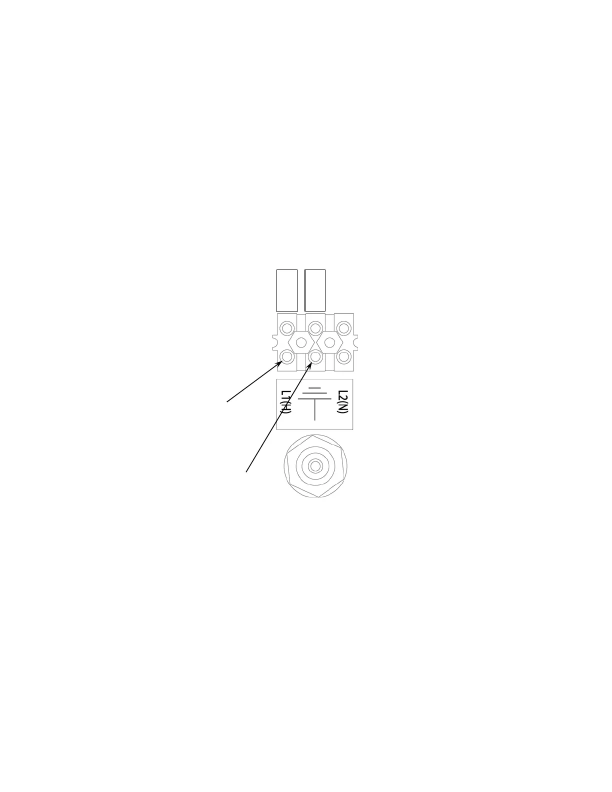
Strip ¼” of insulation from each of the power source positive and negative wires. Solder tin
each wire. Connect the positive (+) voltage source wire to the terminal marked L1(H) on the
terminal block as shown below. Connect the negative (-) voltage source wire to the terminal
marked GND on the terminal block as shown in Figure No. 14 below.
The indicator can be operated as described in this manual.
Figure No. 14
Negative Wire
Positive Wire
R
E
D
B
L
K

 Loading...