8200-M129-O1 Rev D 205 Installation & Technical 10
INSTALLATION, CONT.
Serial I/O Cable Installation
The 205 indicator may be connected to a printer to record weight and associated data or it may
be connected to a remote display or to a computer for transmission of weight data. The weight
data may be transmitted on demand (pressing the PRINT key or on receipt of a command from
the computer). Refer to the Setup, SIO Serial I/O section of this manual.
1. Remove the 12 acorn nuts securing the back panel to main housing, and then loosen a
gland connector for the serial cable. Refer to Figure No. 2 for illustration of connector
layout.
2. Slip the serial cable through the gland connector and into the enclosure.
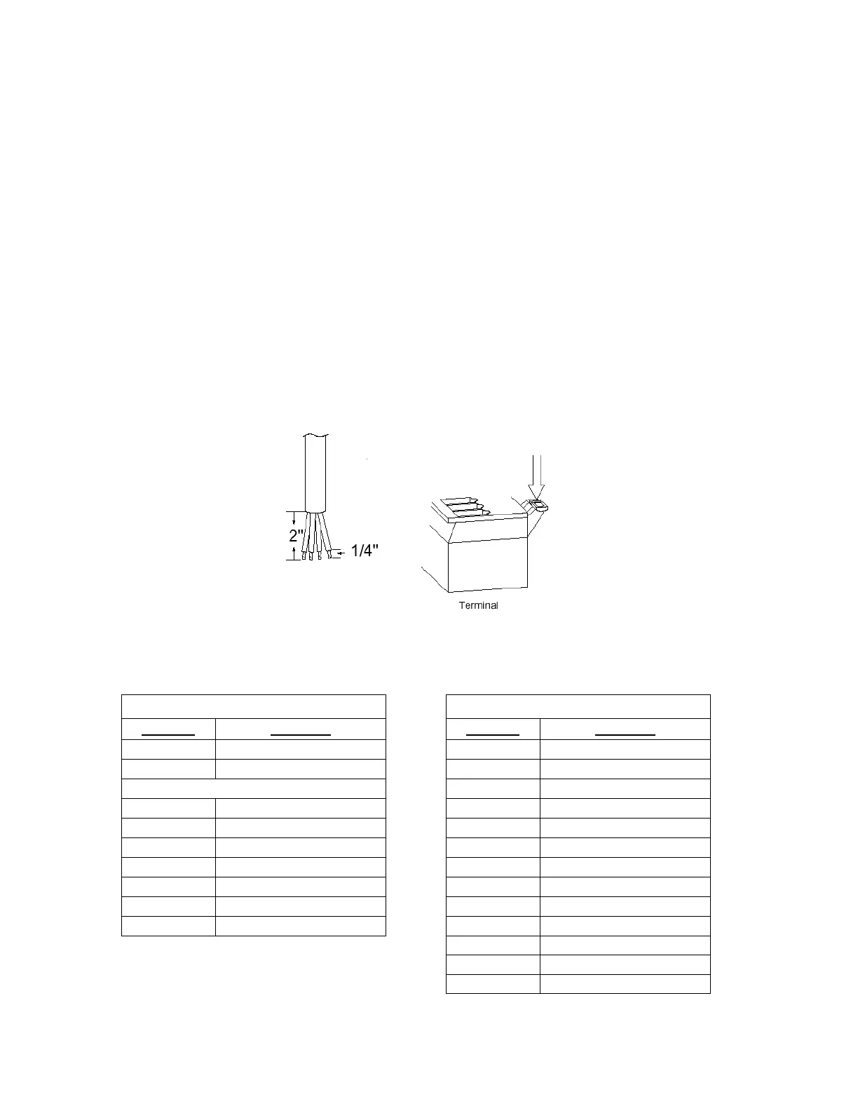
3. Remove 2" of the outer insulation jacket then remove 1/4" of insulation from each of the
wires (refer to the Figure No. 6).
4. Connect each of the wires to the Serial Data terminal block (P13 and P14) referring to
Figure No. 10 for terminal block locations.
5. To terminate, first press down on the release bar for the terminal, insert the wire into the
opening then allow the release bar to return to its original position, locking the wire in place.
Repeat the procedure until all of the wires are in place.
Figure No. 6
BI-DIRECTIONAL SERIAL INTERFACE
TERMINAL (P14) TERMINAL (P13)
PIN NO. Function PIN NO. Function
1
TxD1-RS232
1
+20mA SRC
2
RxD1-RS232
2
RxD0-SRC
3
GND
3
RxD0-20mA+
4
TxD2-RS232
4
RxD0-20mA-
5
RxD2-RS232
5
TxD0-SRC
6
GND
6
TxD0-20mA+
7 TxD3-RS232 7 TxD0-20mA-
8
RxD3-RS232
8
TxD1-20mA+
9 GND 9 TxD1-20mA-
10
GND
11
TxD0-RS232
12
RxD0-RS232
13 GND

 Loading...