4
8. A gas--fired furnace for installation in a residential garage
must be installed as specified in the warning box in the
“Location” section.
9. The furnace may be used for construction heat provided that
the furnace installation and operation complies with the first
CAUTION in the LOCATION section of these instruc-
tions.
10. These Multipoise Gas--Fired Furnaces are CSA design--cer-
tified for use with natural and propane gases (see furnace
rating plate) and for installation in alcoves, attics, base-
ments, closets, utility rooms, crawlspaces, and garages. The
furnace is factory --shipped for use with natural gas. A CSA
(A.G.A. and C.G.A.) listed accessory gas conversion kit is
required to convert furnace for use with propane gas.
11. See Table 1 for required clearances to combustible con-
struction.
12. Maintain a 1--in. (25 mm) clearance from combustible ma-
terials to supply air ductwork for a distance of 36 in. (914
mm) horizontally from the furnace. See NFPA 90B or local
code for further requirements.
Table 1 – Minimum Clea rances to Combustible Materials for
All Units
POSITION CLEARANCE
Rear 0(0mm)
Front (Combustion air open-
ings in furnace and in struc-
ture)
1in.(25mm)
Required for service *24 in. (610 mm)
All Sides of Supply Plenum *1 in. (25 mm)
Sides 0(0mm)
Vent 0(0mm)
Top of Furnace 1in. (25mm)
*Consult local building codes.
13. These furnaces SHALL NOT be installed directly on carpet-
ing, combustible tile, or any other combustible material oth-
er than wood flooring. In downflow installations, factory
accessory floor base MUST be used when installed on com-
bustible materials and wood flooring. Special base is not re-
quired when this furnace is installed on a manufacturer’s
specified coil assembly or coil box (see furnace clearance
label).
Important Installation and Start--up Procedures
Failure to follow this procedure may result in a nuisance
smoke or odor complaint.
The manifold pressure, gas rate by meter clocking,
temperature rise and operation must be checked after
installation. Minor smoke and odor may be present
temporarily after start-- up from the manufacturing process.
Some occupants are more sensitive to this minor smoke and
odor. It is recommended that doors and windows be open
during the first heat cycle.
NOTICE
INTRODUCTION
This 4--way multipoise Category IV condensing furnace is CSA
design-- certified as a direct--vent (2-pipe) or non-direct vent
(1-pipe) furnace. See Fig. 2. The furnace is factory --shipped for
use with natural gas. The furnace can be converted in the field for
use with propane gas when a factory-supplied conversion kit is
used. Refer to the furnace rating plate for conversion kit
information.
This furnace is not approved for installation in mobile homes,
recreational vehicles, or outdoors.
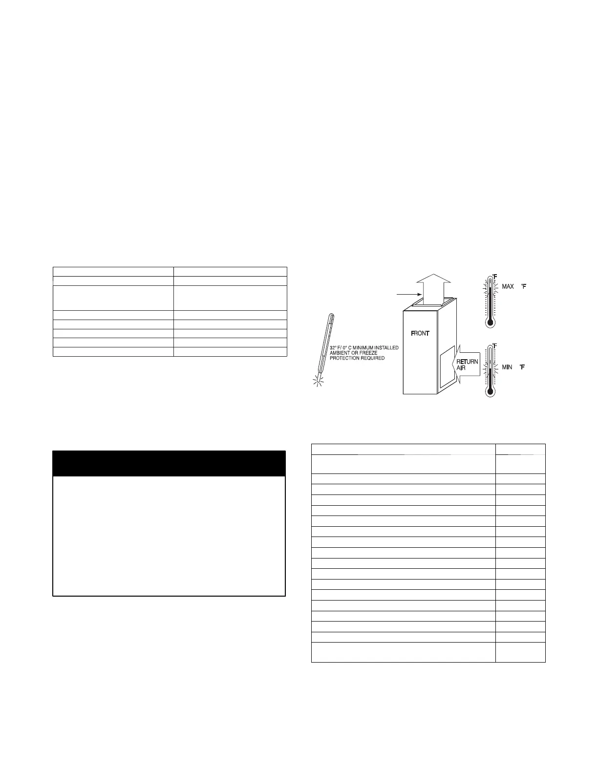
This furnace is designed for minimum continuous return--air
temperature of 60_F(15_C) db or intermittent operation down to
55_F(13_C) db such as when used with a night setback
thermostat. Return-air temperature must not exceed 80_F(27_C)
db. Failure to follow these return-air temperature limits may af fect
reliability of heat exchangers, motors, and controls. See Fig. 1.
The furnace should be sized to provide 100 percent of the design
heating load requirement plus any margin that occurs because of
furnace model size capacity increments. None of the furnace
model sizes can be used if the heating load is 20,000 BTU or
lower. Use Air Conditioning Contractors of America (Manual J
and S); American Society of Heating, Refrigerating, and
Air-Conditioning Engineers; or other approved engineering
method to calculate heating load estimates and select the furnace.
Excessive oversizing of the furnace may cause the furnace and/or
vent to fail prematurely, customer discomfort and/or vent freezing.
Failure to follow these guidelines is considered faulty installation
and/or misapplication of the furnace; and resulting failure, damage,
or repairs may impact warranty coverage.
For accessory installation details, refer to the applicable instruction
literature.
NOTE: Remove all shipping materials, loose parts bag, and
literature before operating the furnace. See Table 2.
60
80 / 27˚C
/ 16˚C
SUPPLY AIR
SEE PRODUCT DATA FOR
ACCESSORY CONDENSATE
TRAP HEATER AND CONDENSATE
DRAIN LINE PROTECTION.
A150573
Fig. 1 -- Freeze Protection and Return Air Temperature
Table 2 – Loose Parts Bag
DESCRIPTION QUANTITY
Outlet R estrictor Plate (provided with 40K BTUH
furnaces only; see Note)
1
AirIntakePipeFlange 1
Vent Pipe Flange 1
Pipe Flange Gaskets 2
Sharp Tip Screws (Vent and Inlet Flanges) 10
Vent Pipe Coupling 1
Vent Pipe Coupling Clamps 2
Pressure Switch Tube 1
Rubber Drain Elbow 1
Drain Tube Clamps 4
1 / 2 --- i n . C P V C t o 3 / 4 --- i n . P V C P i p e A d a p t e r 1
Gas Line Grommet 1
Junction Box Cover 1
Junction Box Base 1
Green Ground Screw 1
Blunt Tip Screws (Junction Box) 3
Thermostat Wire Grommet 1
Drain Extension Tube (Z---pipe) (Provided separ-
ately in furnace)
1
NOTE: The 40K models are the only furnaces that receive the
outlet restrictor in loose parts bag. See Maximum Equivalent Vent
Length Table for usage.

 Loading...