59
A190032
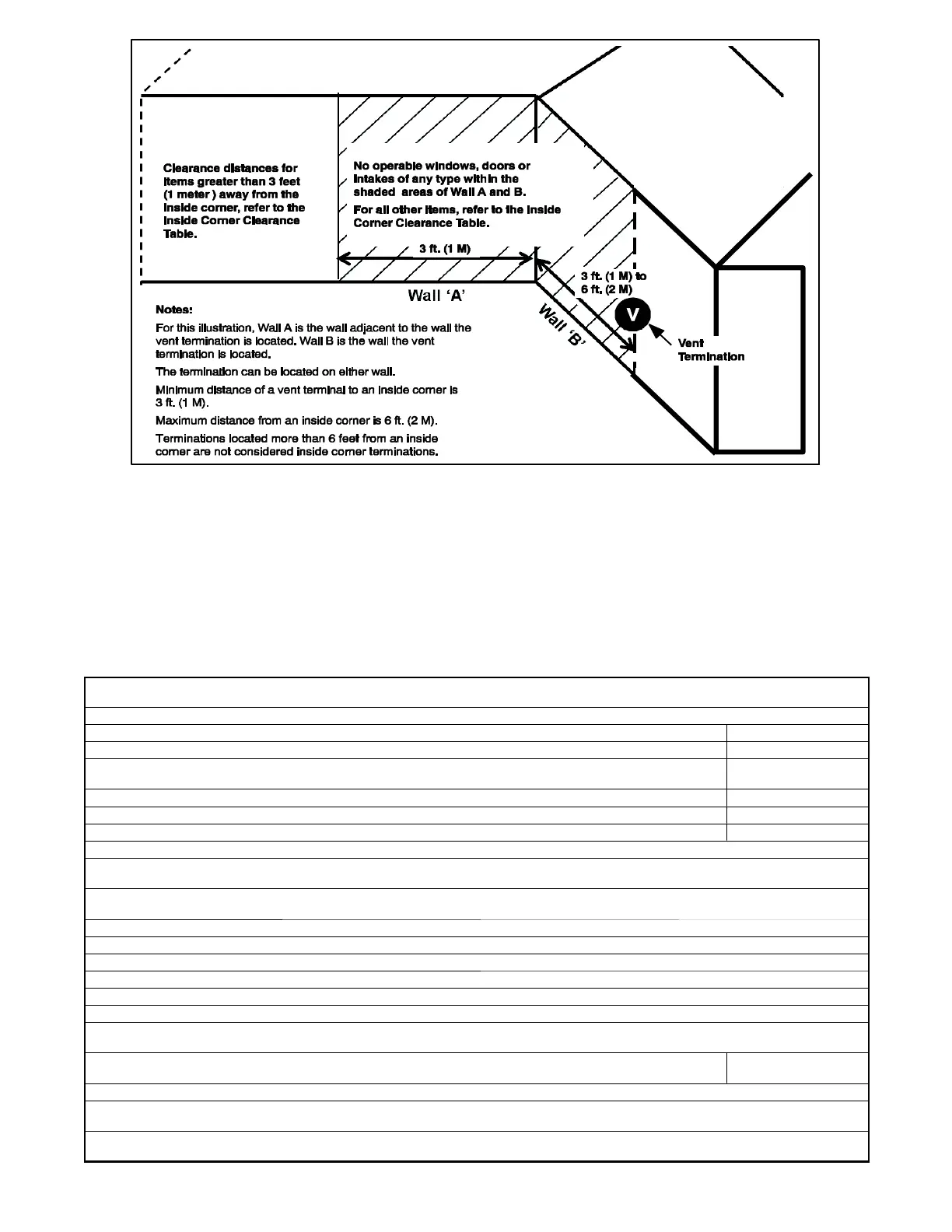
Fig. 51 -- Inside Corner Termination
Inside Corner Terminations
Inside corner vent terminations are permitted provided that:
S Only two exterior walls come together to form an angle of 90 degrees to 135 degrees. There are no other exterior walls
attached to either wall to form an alcove.
S The clearance distances apply when the vent is at least 3 feet (1 meter) from, but not more than 6 feet (2 meters) away from an
inside corner.
S F or vent terminations located more than 6 feet (2 meters) from an inside corner, refer to the appropriate Direct Vent Clearance
Table for all two pipe terminations or Non---Direct Vent Clearance Table for all single pipe terminations.
S The clearance distances to items between the vent termination and the outside corner, refer to the appropriate Direct Vent
Clearanc e Table for all two pipe terminations or Non---Direct Vent Clearance Table for all single pipe terminations.
For clearance distances when vent termination is located more than 6 ft. (2 M) away from an inside corner, refer to the appropriate Direct Vent or
Non---Direct V ent Clearance Table.
Clearance description when termination is at least 3 ft. (1 M) away and not more than 6 ft. (2 M) away from an inside corner.
Clearance above grade, veranda, porch, deck, balcony or anticipated snow level 12---in. (305 mm)
Clearance to a permanently closed window on either Wall A or Wall B 12---in. (305 mm)
Vertical clearance to a soffitt located above the vent termination within a horizontal distance of 2 ft. (61 cm) from the centerline of
the ven t termination
6ft.(2M)
Clearance to a ventilation exhaust (including HRV/ERV) on either Wall A or Wall B 12---in. (305 mm)
Clearance above paved sidewalk or paved driveway located on public property 7ft.(2.1M)
Clearance under a veranda, porch, deck, or balcony N.P.*
No operable windows, doors or intakes of any type are permitted on Wall B between the vent termination and the inside corner when the vent
termination is at least 3 ft. (1 M) away and not more than 6 ft. (2 M) away from an inside corner.
The following items on Wall A must be located at least 3 ft. (1 M) away from the inside corner when a vent termination is located on Wall B and the
vent termination is at least 3 ft. (1 M) away or not more than 6 ft. (2 M) away from an inside corner.
A window or door that may be opened
The centerline extended above electrical meter or gas service regulator assembly
A service regulator vent outlet
The centerline of a dryer or water h eater vent, or other appliance’s vent intake
A non ---mechanical air supply inlet
Clearance distances shown for Wall A are measured horizontally from the exit of the termination on Wall B to the closest edge of the item shown
below.
Clearance to a mechanical air supply (including HRV/ERV) inlet unless termination is 3 ft. (1 M) above the horizontal line of the
intake
10 ft. (3 M)
For clearance distances from a vent termination to the outside corner of the wall, refer to the appropriate Direct Vent or Non--- Direct Vent Clearance
Ta b l e
*N.P. = Not Permitted
*N/A = Not Applicable

 Loading...