53
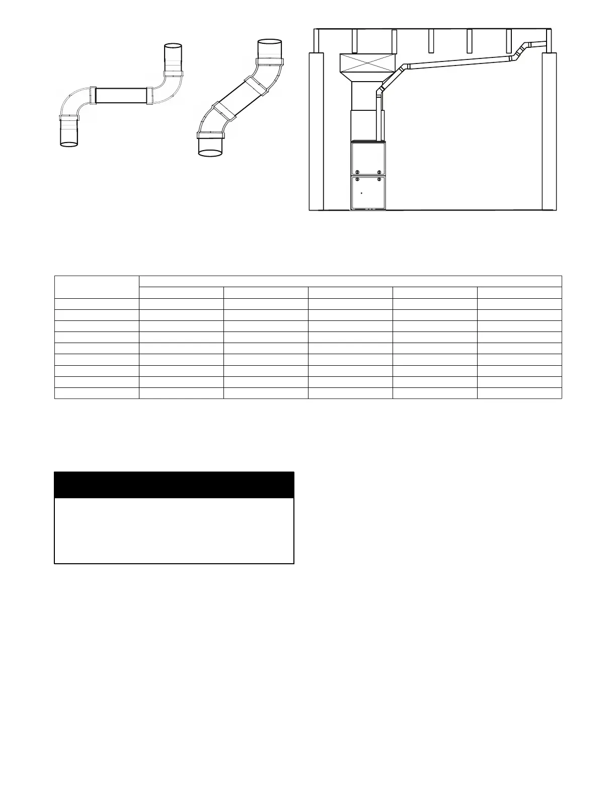
Avoid short horizontal osets with 90
deg. Elbows. Short osets can be
dicult to slope and may trap con-
densate.
Use 45 deg. Elbows where
possible, to ensure conden-
sate drainage.
Slope vent pipe back to the
furnace at least ¼” per foot
A14546
Fig. 49 -- Near Furnace Vent Connections
Table 14 – Hanger Spacing
Diameter
Material
PVC Sch 40 SDR 21 & 26 ABS CPVC Polypropylene
11/2--in. 3--ft. 2 1/2--ft. 3--ft. 3--ft. 3.25--ft.
38--mm 914--mm 762--mm 914--mm 914--mm 1000 mm
2--in. 3--ft. 3--ft. 3--ft. 3--ft. 3.25--ft.
51--mm 914--mm 914--mm 914--mm 914--mm 1000 mm
21/2--in. 3 1/2--ft. 3--ft. 3 1/2--ft. 3 1/2--ft. 3.25--ft.
64--mm 1067--mm 914--mm 1067--mm 1067--mm 1000 mm
3--in. 3 1/2--ft. 3--ft. 3 1/2--ft. 3 1/2--ft. 3.25--ft.
76--mm 1067--mm 914--mm 1067--mm 1067--mm 1000 mm
4--in. 4--ft. 3 1/2--ft. 4--ft. 4--ft. 3.25--ft.
8. Slide the end of the rubber vent coupling with notches in it
over the standoffs on the vent pipe adapter.
9. Insert a length of vent pipe through the coupling into the
outlet of the vent elbow.
10. Tighten the clamp around the outlet of the vent elbow.
Torque the clamp to 15 lb--in.
The following instructions are for PVC/ABS DWV vent
piping o nly. DO NOT USE THESE TECHNIQUES FOR
POLYPROPYLENE VENT PIPING SYSTEMS. See the
polypropylene vent system manufacturer ’s instructions for
installing polypropylene venting systems.
NOTICE
Install the remaining vent and combustion air pipes as shown
below. It is recommended that all pipes be cut, prepared, and
pre--assembled before permanently cementing any joint.
1. Working from furnace to outside, cut pipe to required
length(s).
2. De--burr inside and outside of pipe.
3. Chamfer outside edge of pipe for better distribution of
primer and cement.
4. Complete the vent and combustion air pipe installation by
connecting the concentric vent or by installing the required
termination elbows as shown in Figs. 54, 55 and 56.
For Ventilated Combustion Air Termination, see Fig. 57.
5. Clean and dry all surfaces to be joined.
6. Check dry fit of pipe and mark insertion depth on pipe.
7. Insert the vent pipe into the vent elbow.
8. Torque clamp on vent elbow 15 lb-- in.
9. Torque clamp on vent coupling 15 lb --in.
10. Insert the combustion air pipe into the adapter.
11. Pilot drill a screw hole through the adapter into the combus-
tion air pipe and secure the pipe to the adapter with sheet
metal screws. DO NOT DRILL INTO POLYPROPY-
LENE VENT PIPES. Use an optional accessory vent cou-
pling, if needed.
12. Seal around the combustion air pipe with silicone or foil
tape. SILICONE SEALERS MAY NOT BE APPRO-
PRIATE FOR POLYPROPYLENE VENT SYSTEMS.
SEE POLYPROPYLENE VENT SYSTEM MANU-
FACTURER’S INSTRUCTIONS.
13. After pipes have been cut and pre--assembled, apply gener-
ous layer of cement primer to pipe fitting socket and end of
pipe to insertion mark. Quickly apply approved cement to
end of pipe and fitting socket (over primer). Apply cement
in a light, uniform coat on inside of socket to prevent
buildup of excess cement. Apply second coat. DO NOT
CEMENT POLYPROPYLENE FITTINGS.
14. While cement is still wet, twist pipe into socket with 1/4--in.
turn. Be sure pipe is fully inserted into fitting socket.
15. Wipe excess cement from joint. A continuous bead of ce-
ment will be visible around perimeter of a properly made
joint.
16. Handle pipe joints carefully until cement sets.
17. Horizontal portions of the venting system shall be
supported to prevent sagging. Space combustion air piping
and vent piping hangars as shown in Table 14. Support
pipes using perforated metal hanging strap or commercially
available hangars or straps designed to support plastic pipe.
18. Slope the vent and combustion air piping downward
towards furnace. A minimum slope of at least 1/4-in. (6

 Loading...