70
operation. The mode of operation is based on the position of Setup
Switch SW1--2 o n the furnace control board.
3. This furnace is capable of automatically providing proper
airflow to maintain the temperature rise within the range
specified on furnace rating plate. If temperature rise is
outside this range, proceed as follows:
a. Check gas input for low-- and high--heat operation.
b. Check derate for altitude, if applicable.
c. Check allreturn and supply ducts for excessive restrictions
causing static pressure greater than 0.5--In. W.C.
d. Ensure Comfort/Efficiency SW1-- 4 on furnace control is
in OFF=Efficiency position when a bypass humidifier is
used. See Fig. 39 for switch location.
e. Verify correct model plug is installed.
To lock the furnace in low heat:
1. Turn SW1-- 2 ON at the furnace control.
2. Connect a jumper across R and W/W1 at the thermostat
terminals at the furnace control.
3. Allow the burners to ignite and the blower to turn on.
4. Allow the supply temperature to stabilize and verify the
proper rise range.
If the temperature rise is too high or too low in low heat:
1. Remove jumpers from R and W/W1.
2. Wait until the blower off delay is completed.
3. Turn 115 VAC power off.
4. Check the position of setup switch SW1--4. When set to
OFF, airflow is raised 7% for low heat Factory default
position is ON.
5. Turn 115 VAC power on.
6. Re--check low heat temperature rise.
To lock the furnace in high heat:
1. Connect a jumper across R and W/W1 and W2 at the
thermostat terminals at the furnace control.
2. Allow the burners to ignite and the blower to turn on.
3. Allow the supply temperature to stabilize and verify the
proper rise range.
If the temperature rise is too high or too low in high heat:
1. Remove jumpers from R and W/W1 and W2.
2. Wait until the blower off delay is completed.
3. Turn 115 VAC power off.
4. Check the position of setup switch SW1--4. When set to
OFF, airflow is raised 7% for low Heat, and 10% for high
heat. Factory default position is ON.
5. Turn 115 VAC power on.
6. Re--check high heat temperature rise.
After the temperatur e rise has been verified:
1. Remove jumpers from thermostat terminals.
2. Allow the blower off delay to complete.
3. Turn setup switches SW1--2 to the OFF position unless
two--stage thermostat operation is desired. See Fig. 65.
4. Proceed to “Adjust Blower Of f Delay” or install blower
door if complete.
Adjust Blower Off Delay (Heat Mode)
1. Remove blower door if installed.
2. Turn Dip switch SW--7 or SW--8 ON or OFF for desired
blower off delay. See Table 19 and Fig. 39, 65 and 73.
Adjust Cooling Airflow – High-Speed and
Low-Speed
Cooling
The ECM blower can be adjusted for a range of airflows for
low-speed or high-speed cooling. See Table 9 – Air Delivery –
CFM (With Filter) and Fig. 65 – Furnace Setup Switches and
Descriptions. Depending on the model size, the cooling airflow
can be adjusted from 1.5 to 6 tons based on 350 CFM per ton.
NOTE: 6 ton airflow will truncate at 2200 CFM on applicable
models.
The h igh-speed or single-speed cooling airflow is adjusted by
turning Setup switches SW2--6, SW2--7 and SW2--8 either ON or
OFF. Select the required airflow from Table 9. Table 9 is based
upon 350 CFM per ton. For other CFM per ton Setup switch
selections, see Fig. 39, 65 and 73.
The Continuous Fan airflow selection via Setup switches SW2 is
also the airflow for low-speed cooling when the furnace is used
with a 2-speed cooling or heat pump unit. Adjust SW2--3, 4, 5 to
match the airflow required for low-speed cooling. Select the
required airflow from Table 9 and Fig. 65.
NOTE: The airflow selected via SW2--3, 4, 5 (Low-Speed
Coolin g Airflow) cannot exceed the airflow selected via SW2--6, 7,
8 (High-Speed Cooling Airflow). For other CFM per ton Setup
switch selections, see Fig. 39 and 65.
NOTE: The airflow settings for SW2 --6, 7, 8 and SW2 --3, 4, 5
selections are the same, EXCEPT for the default values. See T a ble
9.
For a complete explanation of cooling airflow, refer to the section
titled “Sequence of Operation.”
Adjust Continuous Fan Airflow (and Low-Speed
Cooling
Airflow)
Adjust continuous fan and low-- stage cooling airflow using
SW2--3, 4, 5 and refer to Fig. 65. The continuous fan speed can be
further adjusted at a conventional thermostat using the continuous
fan speed select function. Changing the continuous fan speed at a
conventional thermostat DOES NOT change the low-speed
cooling airflow selected via SW2 at the control board.
Refer to the section titled “Continuous Blower Speed Selection for
Thermostat.”
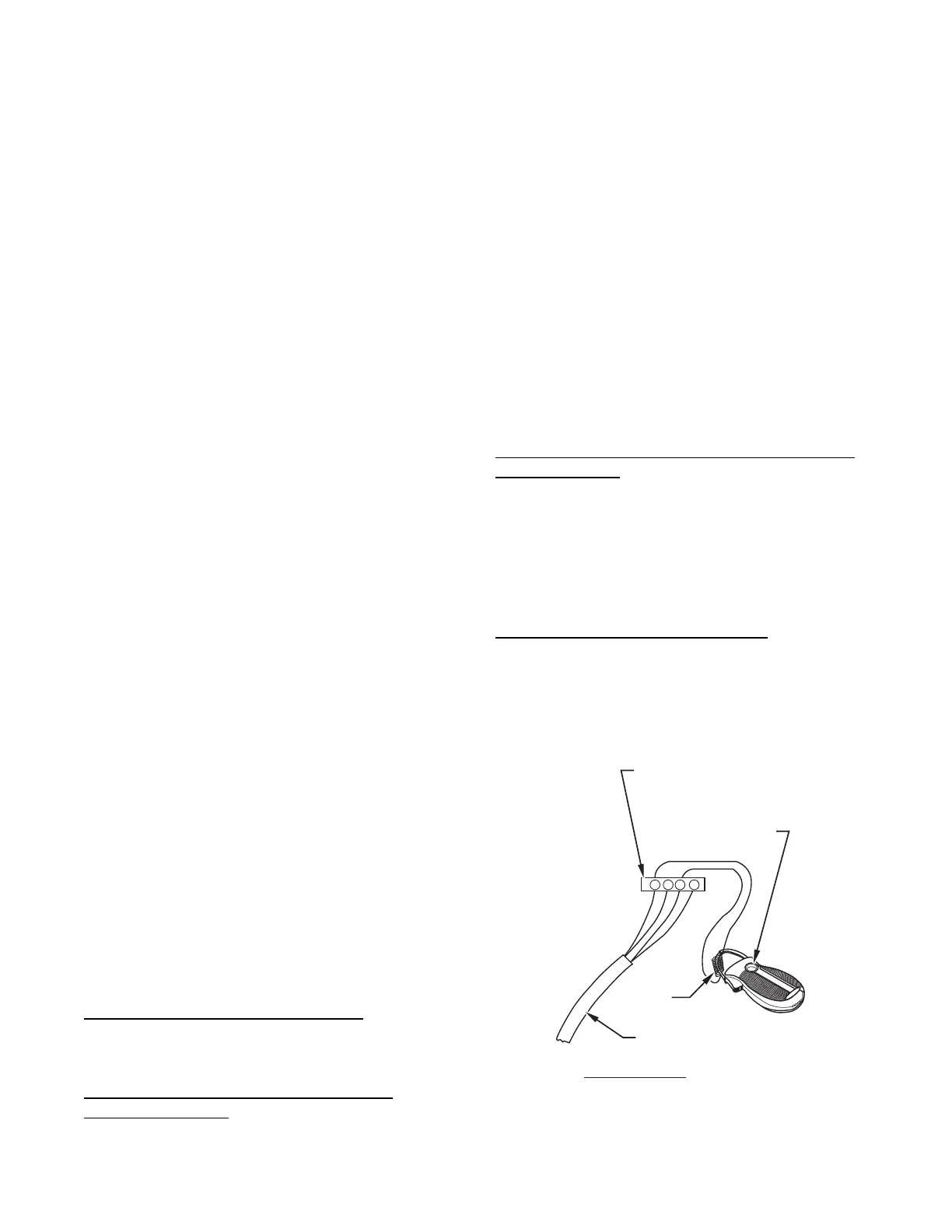
Adjust Thermostat H eat Anticipator.
1. Mechanical thermostat. Set thermostat heat anticipator to
match the amp. draw of the electrical components in the
R--W/W1 circuit. Accurate amp. draw readings can be
obtained at the wires normally connected to thermostat
subbase terminals, R and W. The thermostat anticipator
should NOT be in the circuit while measuring current.
R Y W G
10 TURNS
THERMOSTAT SUBBASE
TERMINALS WITH
THERMOSTAT REMOVED
(ANITICIPATOR, CLOCK, ETC.,
MUST BE OUT OF CIRCUIT.)
HOOK-AROUND
AMMETER
EXAMPLE:
5.0 AMPS ON AMMETER
10 TURNS AROUND JAWS
=
0.5 AMPS FOR THERMOSTAT
ANTICIPATOR SETTING
FROM UNIT 24-V
CONTROL TERMINALS
A96316
Fig. 63 -- Amp. Draw Check with Ammeter
a. Set SW1 --2 switch on furnace control board to ON.

 Loading...