40
Table 11 – Electrical Data
FURNACE SIZE
V O LT S ---
H E R T Z ---
PHASE
OPERATING VOLTAGE
RANGE*
MAXIMUM
UNIT
AMPS
UNIT
AMPACITY#
MINIMUM
WIRE SIZE
AWG
MAXIMUM
WIRE LENGTH
FT (M)}
MAXIMUM
FUSE OR
CKT BKR
AMPS{
Maximum* Minimum*
040V14--- 10 1 1 5 --- 6 0 --- 1 127 104 7.0 9.7 14 38 (11.7) 15
040V17--- 12 1 1 5 --- 6 0 --- 1 127 104 7.2 9.8 14 37 (11.5) 15
060V14--- 12 1 1 5 --- 6 0 --- 1 127 104 7.1 9.7 14 38 (11.7) 15
060V17--- 14 1 1 5 --- 6 0 --- 1 127 104 10.9 14.6 14 25 (7.7) 15
080V17--- 16 1 1 5 --- 6 0 --- 1 127 104 10.0 13.4 14 27 (8.4) 15
080V21--- 20 1 1 5 --- 6 0 --- 1 127 104 14.7/11.2 19.3/14.0
1
12/14
1
29/24
1
(8.8/7.3
1
) 20/15
1
100V21--- 20 1 1 5 --- 6 0 --- 1 127 104 14.8/11.3 19.4/15.0
1
12/14
1
29/24
1
(8.8/7.3
1
) 20/15
1
120V24--- 22 1 1 5 --- 6 0 --- 1 127 104 12.6 16.7 12 34 (10.5) 20
* Permissible limits of the voltage range at which the unit operates satisfactorily.
# Unit ampacity = 125 percent of largest operating component’s full load amps plus 100 percent of all other potential operating components’ (EAC, humidi fier,
etc.) full load amps.
{ T ime---delay type is recommended.
} Length shown is as measured one way along wire path between furnace and service panel for maximum 2 percent voltage drop.
1
Low Amp K it (KGAPC0101ECM) allows select furnaces to be installed with a 15 Amp Breaker and 14 AWG wire within the listed wire length. Affected data
shown as Default Value/Value with Lower Amp Kit.
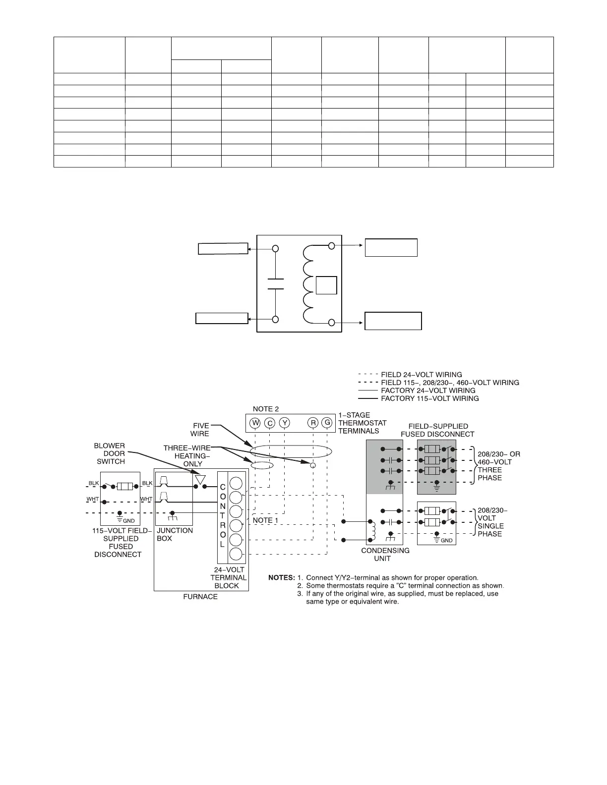
24 V
Coil
To Humidifier Leads
To Com/24V Screw Terminal
on Thermostat Strip
To HUM Terminal On
Furnace Control Board
To Humidifier Leads
A11157
Fig. 37 -- Field--supplied Isola tion Relay for Humidifiers with Internal Power Supply
W/W1
W2
COM
Y/Y2
R
G
A11401
Fig. 38 -- Typical Two --Stage Field Wiring Diagram

 Loading...