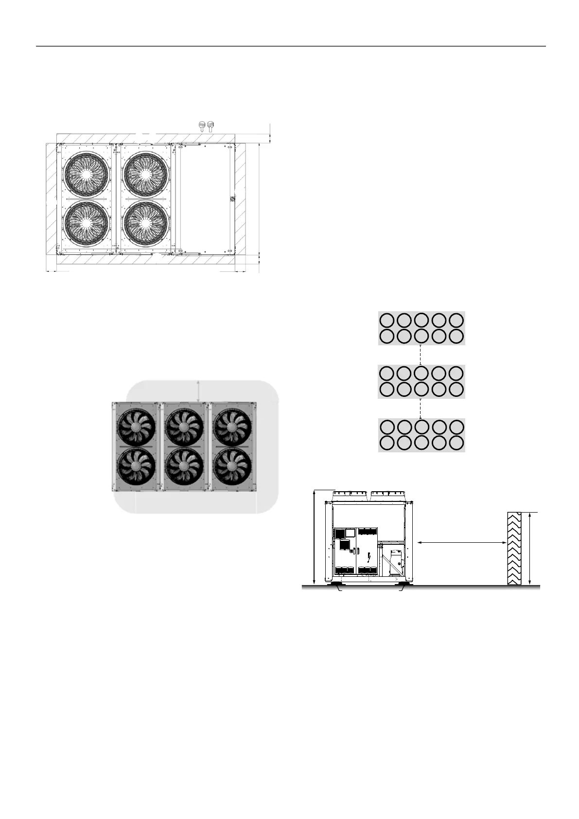
4.3 - Free spaces
The free spaces presented are determined in order to ensure
sucient working and manoeuvring space to carry out maintenance
operations on the unit in suitable ergonomic conditions
2523 HT
1500
2200
1500
1500
B
B
B
B C
Key:
All dimensions are given in mm.
B
Clearances required for maintenance and air ow
C
Clearance recommended for coil removal
4.4 - Positioning of potentially ammable zones
around the unit
Electrical cabinet side
60cm
The complete unit, including all the options and accessories which
are provided by the manufacturer, have been certied for use with
an A2L refrigerant.
To ensure this, the manufacturer complies with EN 378-2 §6.2.14
and has dened a potentially ammable zone using EN 60079-
10-1 in order to identify where no sources of ignition must be
present.
The manufacturer has then designed the machine so that, if the
unit is used in the manner for which it has been designed, there
are no internal sources of ignition in the potentially ammable
zone inside the machine.
Therefore, the only residual risk is that a source of ignition is
introduced into the potentially flammable zone by the user.
This is why the manufacturer has decided to show the potentially
ammable zone around the machine (see the diagram above)
into which the user must not introduce any sources of ignition.
This indication is only provided to help our customers to identify
the limits of the ammability risk.
However, the machine itself does not present any risk of explosion
connected to the use of A2L refrigerant.
Note (the following information is provided by the manufacturer
for guidance only. The application of the following directives is the
sole responsibility of the user):
In compliance with the directives 2009/104/EC and 1999/92/EC,
these zones may be qualied as ATEX zones by the user on the
basis of their own risk analysis, for which they alone remain
responsible. In accordance with the denition given by Annex I of
the directive 1999/92/EC, this zone may be classied as zone 2
since it may consist of a location where an explosive atmosphere
consisting of a mixture of air and ammable substances in the
form of a gas is not liable to occur during normal operation or, if
it does occur, it only occurs for a short period of time.
If additional equipment is required (motorised valve, pump, etc.),
it must be:
■ Installed outside of the dened potentially ammable zone
■ Certied as not being a source of ignition for the refrigerant
used.
4.5 - Installing several units
It is recommended to install multiple units in a single row, arranged
as shown in the example below, to avoid recycling air between
the units. If the oor space does not allow this arrangement, contact
your distributor to assess the various installation options.
1500 mm min.
1500 mm
min.
4.6 - Distance to the wall
Plots
Antivibratiles
H
S
h
To guarantee correct operation in most cases:
If h < H, S minimum = 3 m
If h > H or S < 3 m, contact your distributor to assess the various
installation options.
4 - DIMENSIONS, CLEARANCES, MINIMUM INSTALLATION DISTANCES
11

 Loading...

