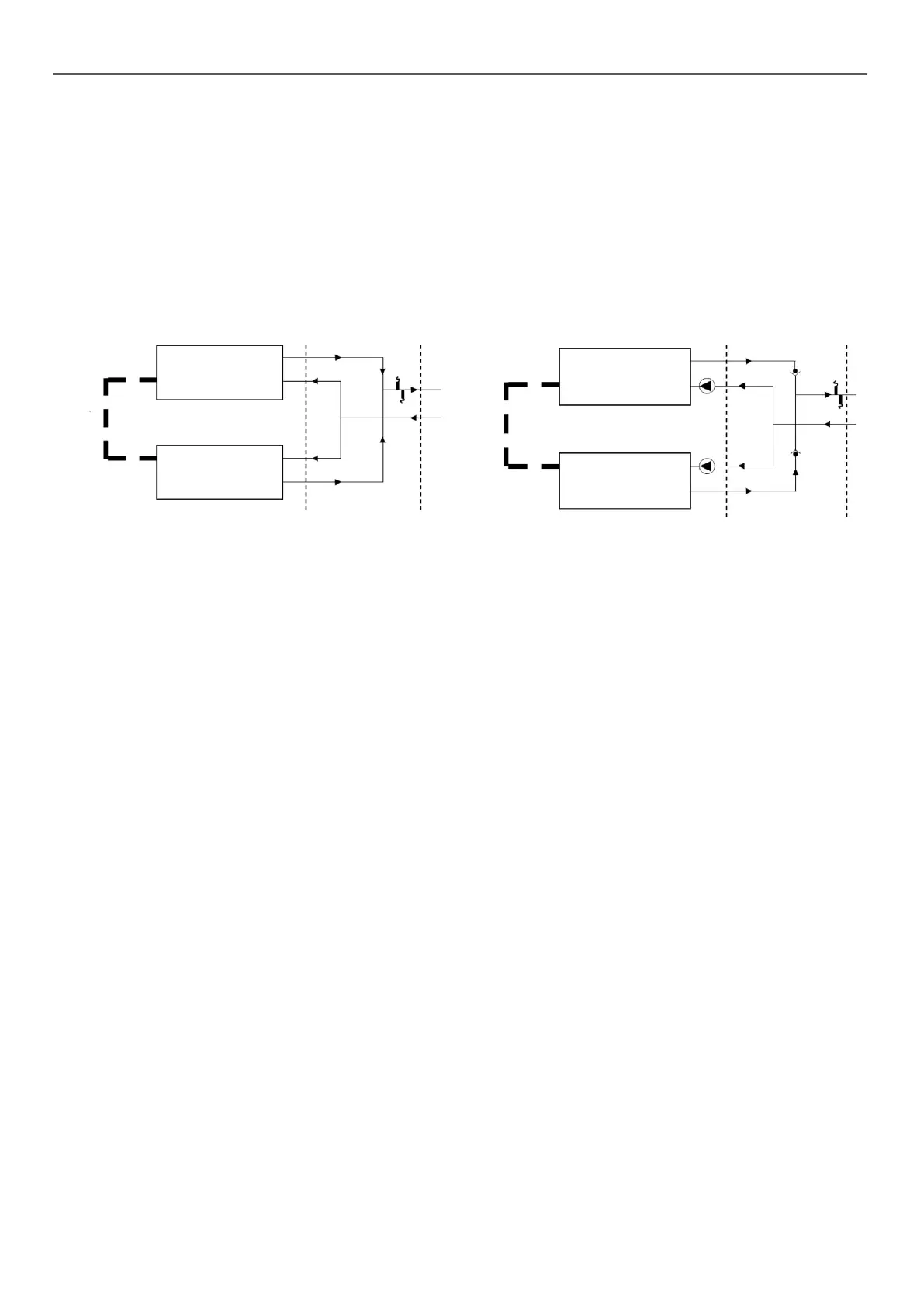
8.3 - Hydraulic connections for 30RQP 620R-1040R units
30RQP 620R – 1040R units are delivered as two separate modules. Two water temperature sensors (one per module) and a
CCN communication bus in the control panel of one of the two modules) are provided.
For optimal operation, we recommend installing the two modules in accordance with the hydraulic diagrams below. The two machines
must be connected in parallel, and the stated performance has been achieved in accordance with this hydraulic installation.
The customer must connect both units via the communication bus. The master and slave modules must be congured and addressed
in the Service conguration menu (refer to the control manual for more details).
We recommend positioning the temperature sensors as shown in the diagrams below to ensure optimal control of the water outlet
temperature.
The temperature sensors must be positioned in an area supplied with water, irrespective of the conditions, to ensure correct control
of the water loop.
Standard unit without hydraulic pump kit
B
C
D
E
F
I J
Standard unit with hydraulic pump kit
B
C
DH
E
H
G
F
I J
G
Key:
B
Module 1
C
Module 2
D
Module 1 water outlet temperature sensor
E
Module 2 water outlet temperature sensor
F
Communication module between the 2 modules (provided)
G
Hydraulic pump kit (116V / 116W option)
H
Check valve
I
Border between the unit and the installation WITHOUT water collection vessel (without option 325)
J
Border between the unit and the installation WITH water collection vessel (with option 325)
Notes: For the hydraulic installation, we recommend following the manufacturer's guidelines (see section 8.1 Precautions
and recommendations for use)
8 - WATER CONNECTIONS
44

 Loading...

