8.2 - Hydraulic connections
The hydraulic module options are only compatible with closed loops.
The use of the hydraulic module on open systems is prohibited.
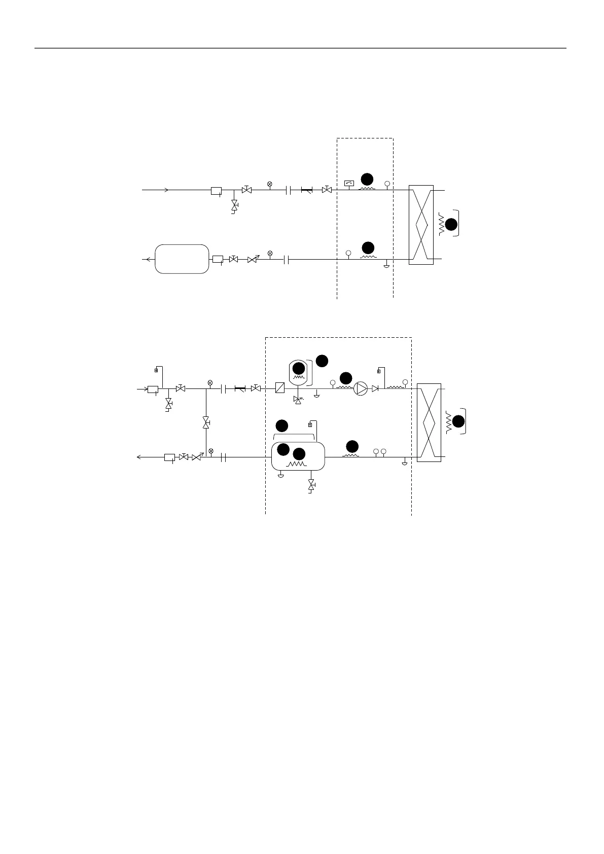
Typical hydraulic circuit diagram without hydraulic module
G
Q
Q
V
V
M
W
I
S
X
JO
T
TT U
Option
Option
Option
Z
N
N
N
T
T
Typical hydraulic circuit diagram with hydraulic module
25
T
T
P
P
B
G
G
G
L
Q
Q
V
V
H
M
R
W
D
I
N
S
S
X
X
E
J
T
T
T
Y
F
F
K
U
N
N
N
N
Z
N
P
C
Option
Option
Option
Option
Option
Option
Key
Components of the hydraulic module and the unit
B
Screen lter (particle size of 1.2 mm)
C
Expansion tank (option)
D
Relief valve
E
Circulating pump (single or dual)
F
Air vent
G
Water drain tap
H
Pressure sensor
Note: Provides pressure information for the pump inlet (see Control manual)
I
Temperature sensor
Note: Provides temperature information for the water exchanger outlet
(see Control manual)
J
Temperature sensor
Note: Provides temperature information for the water type heat exchanger
inlet (see Control manual)
K
Pressure sensor
Note: Provides pressure information for the water exchanger outlet (see
Control manual)
L
Check valve (if dual pump)
M
Plate heat exchanger
N
Heater or heat trace cable for frost protection (Option)
O
Water type heat exchanger ow rate sensor
P
Water buer tank module (Option)
Installation components
Q
Pocket
R
Air vent
S
Flexible connection
T
Shut-o valve
U
800 µm screen lter (mandatory for a unit without a hydraulic module)
V
Pressure gauge
W
Water ow control valve
Note: Not required if hydraulic module with variable-speed pump
X
Charging valve
Y
Bypass valve for frost protection (if shut-o valves are closed (item 19) during
winter)
Z
Buer tank (if required)
---- Hydraulic module (unit with hydraulic module option)
Notes:
- The installation must be protected against frost.
- The unit's hydraulic module and the water type heat exchanger may be
protected (factory-tted option) against frost using electric heaters and
heat trace cables (13)
- The pressure sensors are assembled on connections without Schrader.
Depressurise and drain the system before any work.
8 - WATER CONNECTIONS
42

 Loading...

