Water ow rate adjustment procedure
Once the circuit is cleaned, read the ow rate value on the user
interface and compare it to the theoretical selection value.
If the value of the ow rate read is greater than the specied value,
this indicates that the overall pressure drop in the system is too
low compared to the available static pressure generated by the
pump.
In this case, close the control valve (item 22) and read the new
ow rate value.
Proceed by repeatedly closing the control valve (item 22) until the
nominal ow rate is achieved at the unit's required operation point.
NOTE:
If the network has an excessive pressure drop in relation to
the available static pressure delivered by the unit pump, the
nominal water ow rate cannot be obtained (lower resulting
ow rate) and the dierence in temperature between the water
inlet and outlet of the water type heat exchanger will be
increased
To reduce the installation's hydraulic system pressure drop, it is
necessary to:
■ Reduce the pressure drops of individual components (bends,
level changes, options, etc.) as much as possible;
■ Use the correct pipe diameter;
■ Do not extend the hydraulic systems
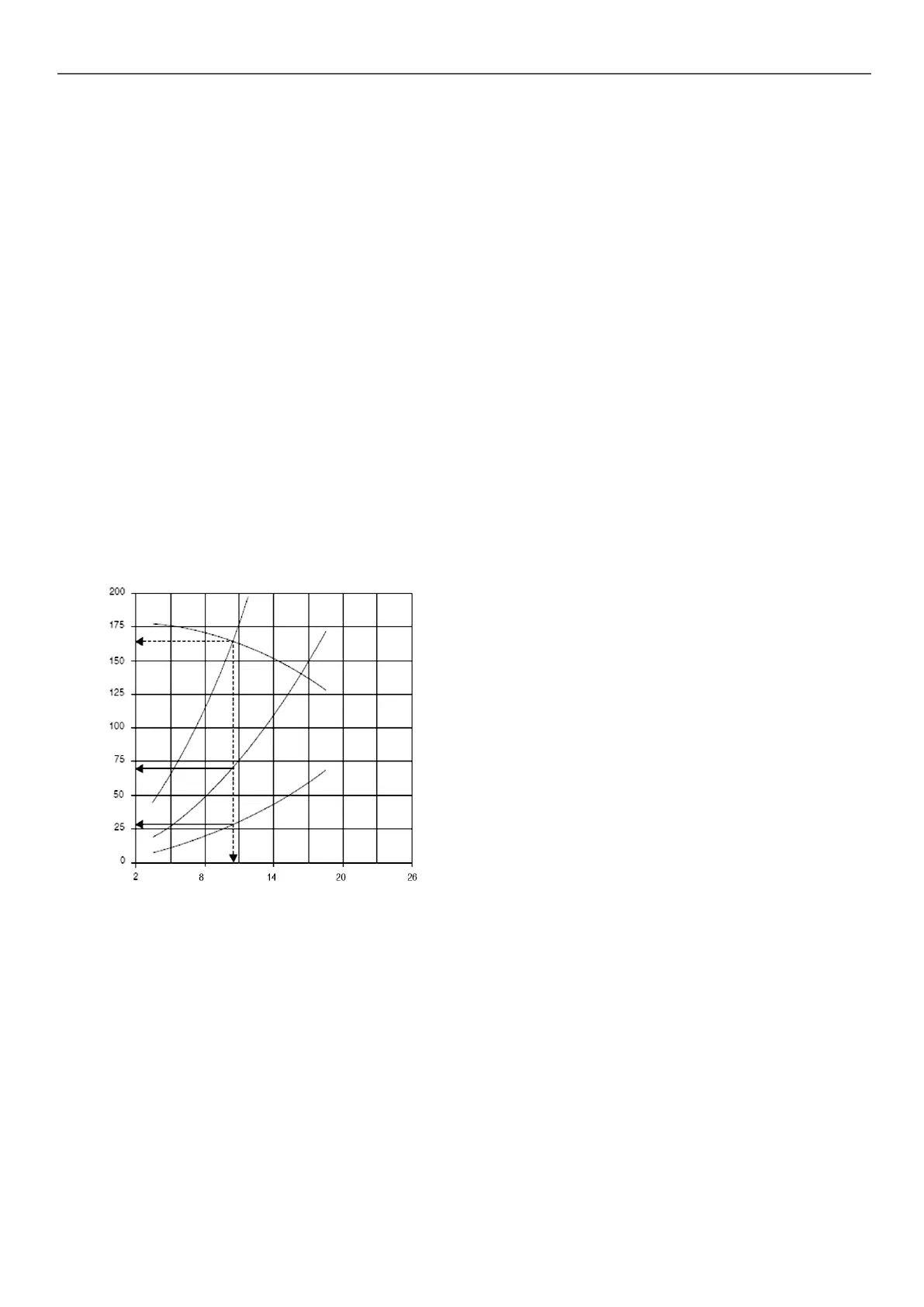
Example: Unit with specied
nominal ow rate of 10.6 l/s
Pressure drop, kPa
Water ow rate, l/s
B
C
D
E
Key
B
Unit pump curve
C
Pressure drop in the hydraulic module (to be measured on the pressure gauge
installed on the water inlet and outlet)
D
Pressure drop in the installation with wide open control valve
E
Pressure drop in the system after setting the valve to obtain the nominal ow
rate specied.
9.3 - Units with hydraulic module and variable-
speed pump – Pressure dierential control
The installation ow rate has not been set to a rated value.
It will be adjusted by the system, by varying the pump speed,
to maintain a constant operating pressure dierential value dened
by the user.
This is checked by the pressure sensor at the outlet of the water
type heat exchanger (item 10 on the typical hydraulic circuit
diagram).
The system calculates the measured pressure difference,
compares it with the setpoint value set by the user and then
modulates the pump speed module accordingly, resulting in:
■ An increase in the ow rate if the measurement is below the
setpoint,
■ A decrease in the ow rate if the measurement exceeds the
setpoint.
This variation in ow rate is limited by the maximum and minimum
permissible ow rate values for the unit and by the maximum and
minimum pump supply frequency values.
The maintained pressure dierence value may, in certain cases,
dier from the setpoint value:
■ If the setpoint value is too high (obtained for a ow rate higher
than the maximum value or a frequency greater than the
maximum value), the system will stop once it reaches the
maximum ow rate or maximum frequency, which will result in
a pressure dierence below the setpoint,
■ If the setpoint value is too low (obtained for a ow rate lower
than the minimum value or a frequency less than the minimum
value), the system will stop once it reaches the minimum ow
rate or minimum frequency, which will result in a pressure
dierence greater than the setpoint.
Contact the manufacturer's Service to implement the procedures
described below
Hydraulic circuit cleaning procedure
Before proceeding, it is advisable to remove any possible
contamination from the hydraulic circuit.
■ Start up the unit pump using the override command.
■ Set the frequency to the maximum value to generate a high
ow rate.
■ If there is a “Maximum ow exceeded” alarm, reduce the
frequency until an acceptable value is reached.
■ Read the ow rate on the user interface.
■ Let the pump run for 2 hours continuously to ush the system's
hydraulic circuit (presence of contaminating solids).
■ Perform another reading of the ow rate and compare this value
with the initial value. A decrease in the ow rate value indicates
that the lters in the system need to be removed and cleaned.
In this case, close the shut-o valves on the water inlet and
outlet (item 19) and remove the lters (items 20 and 1) after
draining the hydraulic part of the unit (items 6).
■ Remove the air from the circuit (items 5 and 17).
■ Repeat until all fouling is removed from the lter
9 - NOMINAL SYSTEM WATER FLOW RATE CONTROL
49

 Loading...

