Refrigerant circuit checks:
■ The unit is subject to F-gas tight regulatory checks. Please refer
to the table in the introduction.
■ Check the unit operating parameters and compare them with
the previous values,
■ Check the operation of the high pressure switches. Replace
them if there is a fault,
■ Check the fouling of the dehumidifier filter. Replace it if
necessary,
■ Keep and maintain a maintenance sheet, attached to each
HVAC unit.
IMPORTANT: Ensure all adequate safety measures are taken
for all these operations: use appropriate PPE (personal
protective equipment), comply with all applicable industry
and local regulations, and use common sense.
13.3 - Level 3 maintenance
Maintenance at this level requires specic skills, qualications,
tools and expertise. Only the manufacturer, his representative or
authorised agent are permitted to carry out this work.
This maintenance work relates to the following:
■ Replacement of major components (compressor, water type
heat exchanger),
■ Operations on the refrigerant circuit (handling refrigerant),
■ Modication of factory-set parameters (change of application),
■ Movement or disassembly of the refrigeration unit,
■ Any operation due to proven lack of maintenance,
■ Any operation covered by the warranty,
■ One or two leak detection operations per year performed by
qualied personnel using a certied leak detector.
■ To reduce waste, the refrigerant and the oil must be transferred
in accordance with applicable regulations, using methods that
limit refrigerant leaks and pressure drops and with materials
that are suitable for the products.
■ Any leaks detected must be repaired immediately
■ The compressor oil that is recovered during maintenance
contains refrigerant and must be treated accordingly.
■ Pressurised refrigerant must not be vented to the open air.
■ If the refrigerant circuit must be opened, cap all openings for a
period of up to one day. If open for longer, blanket the circuit
with a dry, inert gas (e.g. nitrogen).
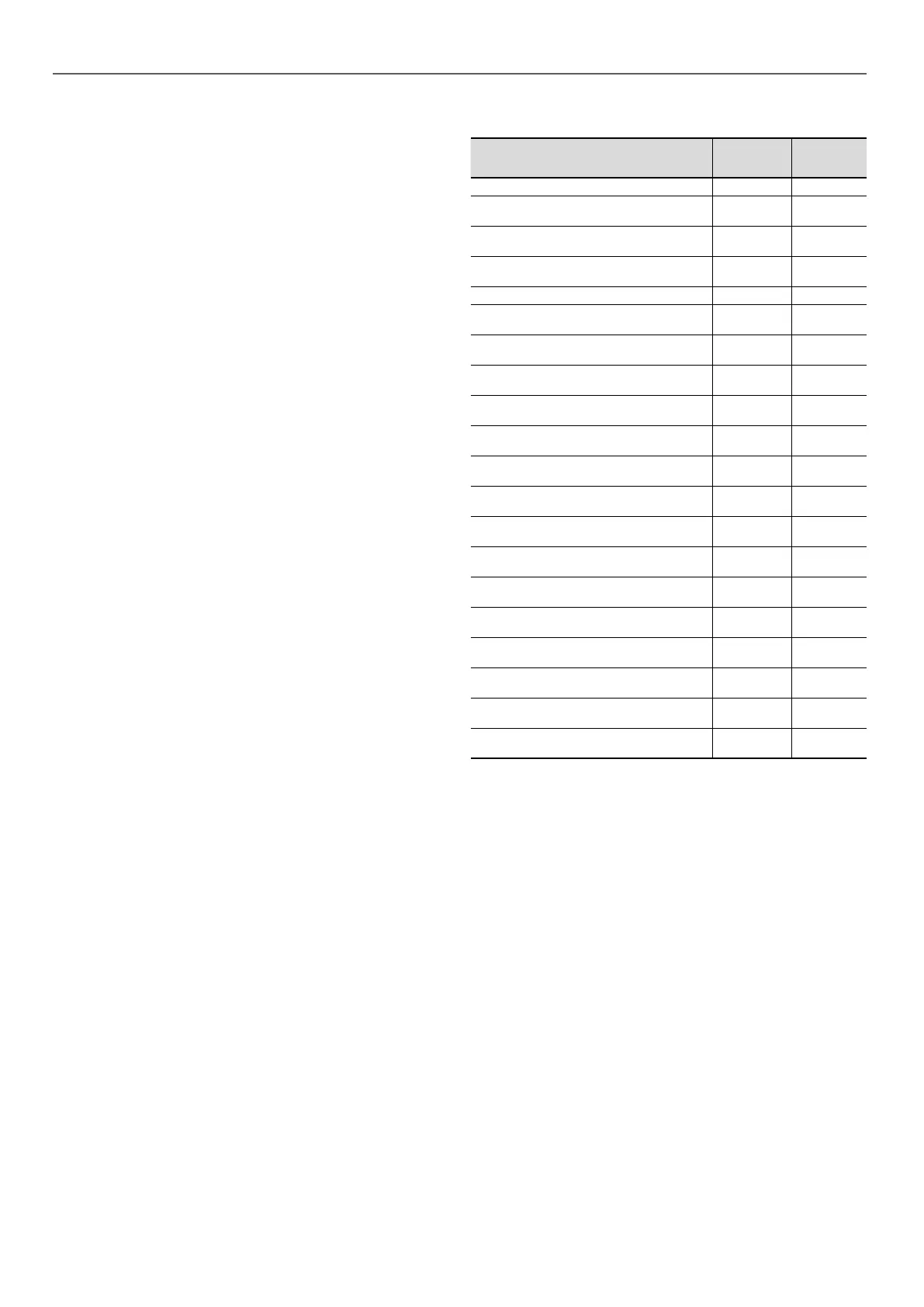
13.4 - Tightening the electrical connections
Component Description Value (N.m)
PE welded screw, customer connection 30
Power supply fuse holder cage screw
terminal
FU - FUA
- FUB
0,5 … 0,8
Power supply circuit breaker cage screw
terminal
QF, QF1 2
Circuit breaker cage screw terminal option
284
QFA 2
Socket cage screw terminal option 284 PC 1,2
Compressor fuse holder cage screw
terminal
FU1 --> FU8 3,5
Compressor contactor cage screw terminal
Size 170R to 550 - Check
KM1-->KM8 1,7
Compressor contactor cage screw terminal
Size 170R to 550 - Power
KM1-->KM8 5
Compressor circuit breakers cage screw
terminal Size 610R to 950R
QM1-->QM8 5
Compressor contactor cage screw terminal
Size 610R to 950R - Check
KM1-->KM8 1,2
Compressor contactor cage screw terminal
Size 610R to 950R - Power
KM1-->KM8 9
Screw terminal, fan circuit breakers
QM11--
>QM62
High 1,7 /
Low 1,3
Variable drive cage screw terminal 1,5 kW,
2,2 kW, 4 kW
GS11 -->
GS22
1,3
Variable drive cage screw terminal 7,5 kW,
11 kW
GS11 -->
GS22
2,5
Variable drive cage screw terminal 15 kW,
18 kW
GS11 -->
GS22
4,5
M6 screw, customer connection (30RB-
RBP and 30RQ-RQP ≤ 170R)
QS101 8
M8 screw, customer connection (180R ≤
30RB-RBP and 30RQ-RQP ≤ 270R)
QS101 15
M10 screw, customer connection (310R ≤
30RQ-RQP ≤ 520R)
QS101 50
M10 screw, customer connection (310R ≤
30RB-RBP ≤ 720R)
QS101 50
M12 screw, customer connection (from
30RB-RBP770R to 30RB-RBP950R)
QS101 75
13 - STANDARD MAINTENANCE
96

 Loading...

